PixelFace
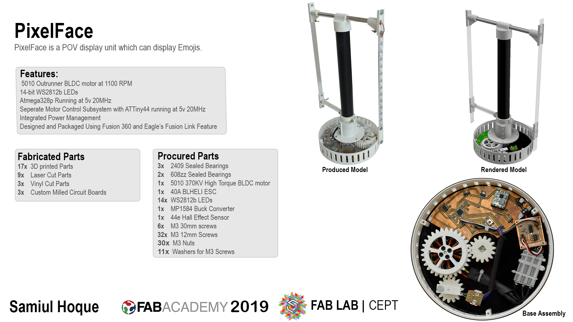
A volumetric persistence-of-vision display. Fourteen addressable LEDs on a pair of acrylic arms spinning at 1100 RPM, drawing a face in the air around a cylinder.
What it is
PixelFace is a volumetric persistence-of-vision display. Two vertical acrylic arms carrying fourteen WS2812B LEDs spin around a central axis at about 1100 RPM. The LEDs are re-written fast enough that the eye stops seeing fourteen moving dots and starts seeing a cylinder of pixels hanging in the air. What it draws on that cylinder is a face.
It was my Fab Academy 2019 final project, built at Fab Lab CEPT in Ahmedabad over the five months of the programme. The weekly build logs are a separate thing: most of the weeks fed parts into this, but the weeks were assignments and this was the machine.
Why a face
The starting idea in week 1 was a universal head for robots. Most hobby robots are a chassis with no front, and a face is the cheapest way to make a machine legible to the person standing next to it. I wanted something a robot builder could bolt on top of an existing project and drive over a couple of wires, that could show an expression rather than blink an RGB LED at you.
A flat screen would have done that. A POV display does it in 360 degrees, so the face is readable from any side, and that is what made it worth building. It is also the reason it was hard. Neil Gershenfeld’s standing comment on POV final projects is that they rarely work, because too many variables have to land at once: rotational speed, positional feedback, LED timing, structural balance, and getting power and data across a spinning joint.
Mechanical build
Everything was modelled in Fusion 360 with each part as a separate file and three assembly files on top, so a dimension change propagated instead of being re-drawn. The machine splits into three parts.
The base assembly holds the motor, the gear drive, the electronics and all the wiring. The base plate and top cover are laser-cut 5mm acrylic; the side ring is 3D printed PLA with cooling grills around it and a cutout for the power jack.
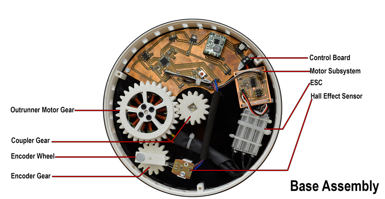
Drive is a 5010 outrunner BLDC and an ESC, which was the wrong choice and I knew it by the end. Every other POV build uses a brushed DC motor. I used a BLDC because I wanted to learn gear transmission and power electronics, and because a 30-tooth gear printed to wrap around the outrunner can, meshing with a 15-tooth gear on the output shaft, gives a clean 2:1 step-up. The cost was that an ESC wants a PWM signal on a schedule, which collides with everything else that is time-critical here. More on that below.
A third 15-tooth gear carries the encoder wheel, which holds a neodymium magnet that passes a 44E hall effect sensor once per revolution. That is the positional reference the whole display is timed against. Each of the 15-tooth gears runs on a pair of 608zz bearings with printed caps locking the inner races to the base.
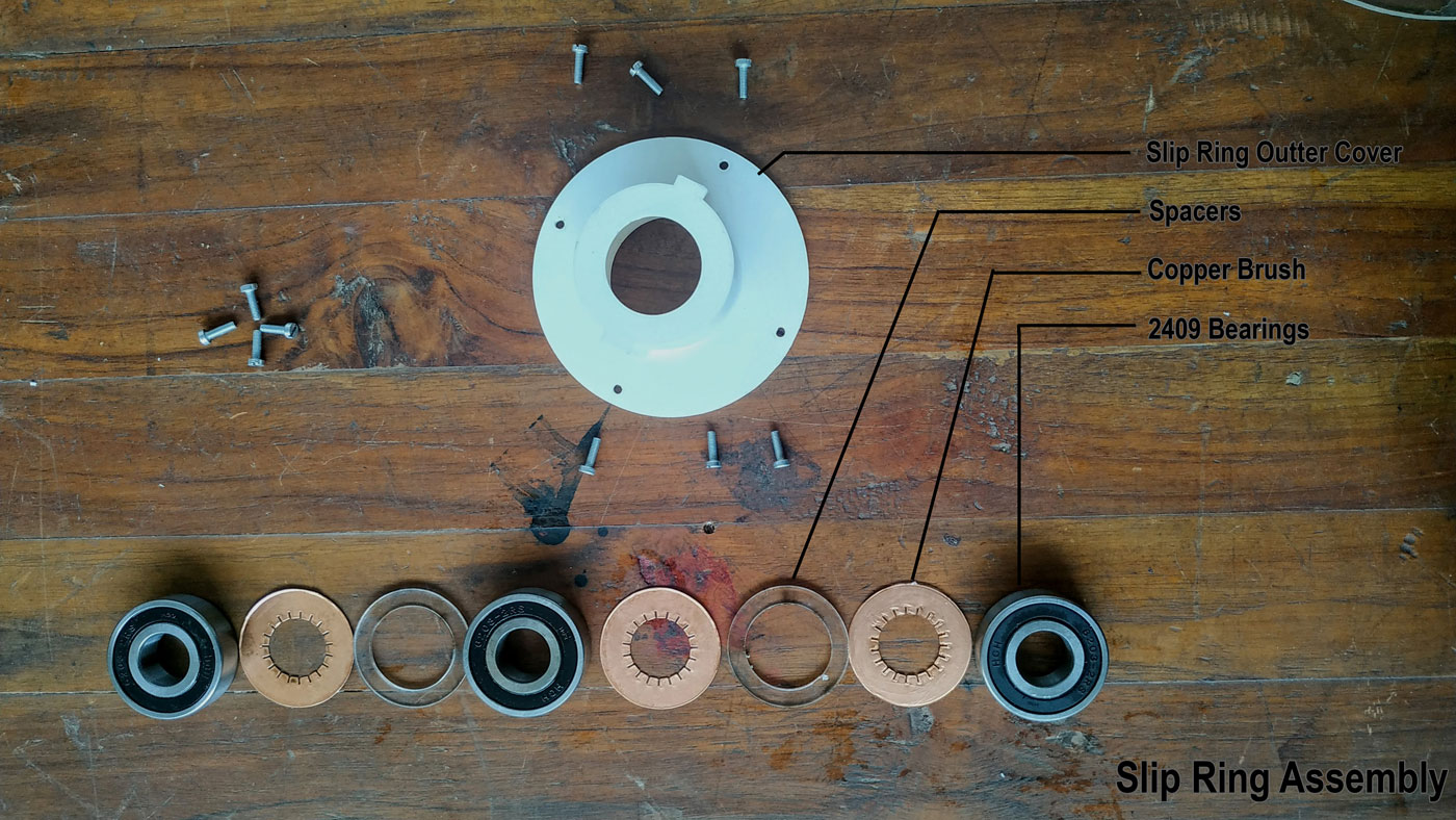
The slip ring was the part I expected to buy and ended up making. It passes power, ground and the LED data line across the rotating joint. Three 2409 bearings are stacked in a printed cover, separated by acrylic spacers that also press copper brushes against the outer races. The brushes are copper tape on 1mm acrylic, cut on the vinyl cutter. Screws through the cover lock the bearings and carry the contact out to the fixed side.
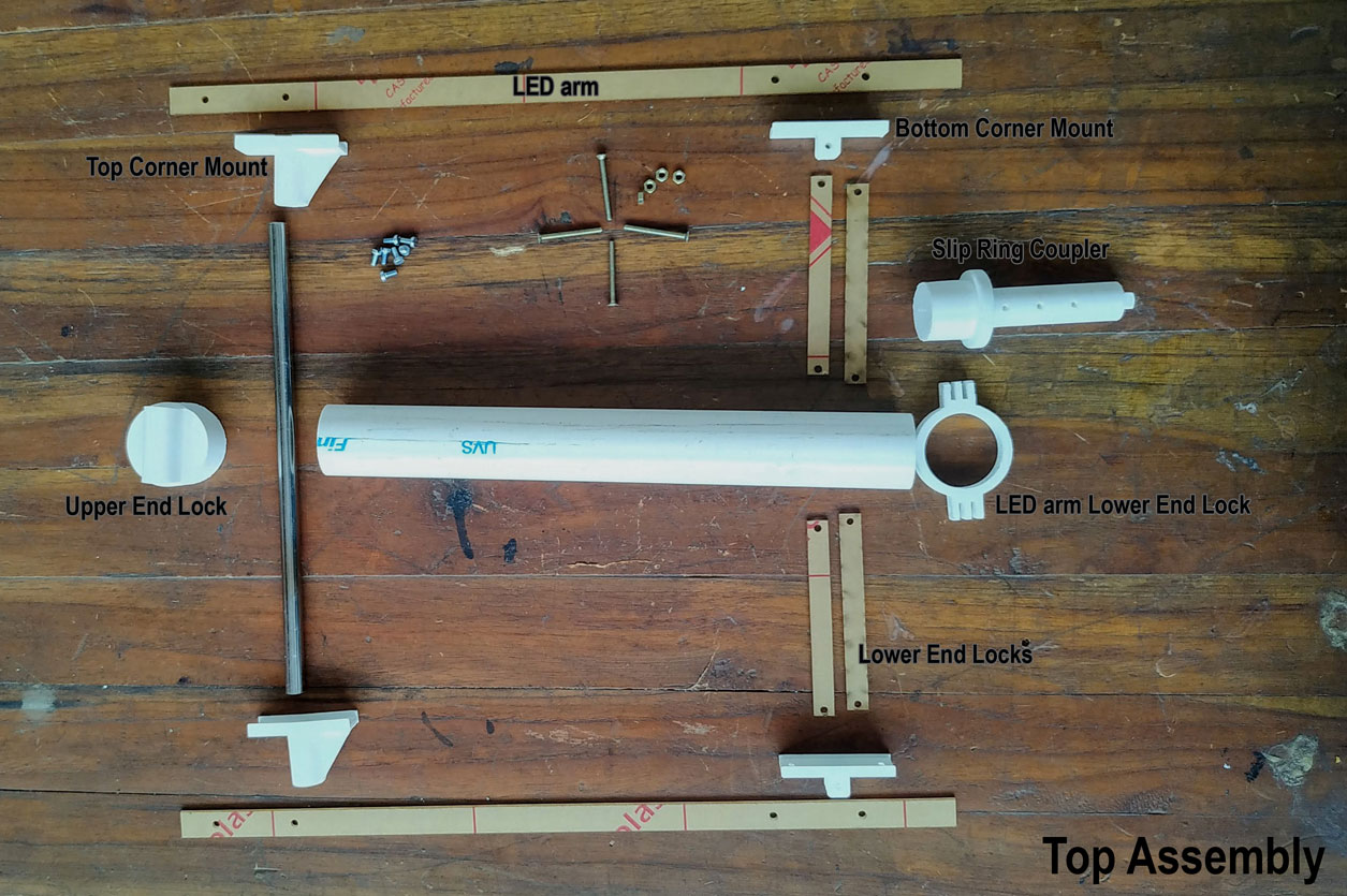
The top assembly is the part that spins. A printed coupler goes up through the slip ring, meshes with the coupler gear below, and has internal channels routing the LED wires. The two LED arms are 2mm acrylic held at both ends by printed corner mounts, with a stainless steel pipe up the middle and four printed locking arms bracing against flex. Locking the arm at both ends rather than cantilevering it off one end is what keeps it from tearing itself apart at 1100 RPM.
Electronics
Three boards, all milled in the lab.
PxFDuino is the main board, an ATmega328P running at 20 MHz. I picked the 328P because it is the Arduino Uno part, so anything that ran on an Uno during development would run here unchanged. v1 came out of output devices week. v2 is the same circuit with the outline redrawn to bolt into the Fusion 360 base, which is the useful trick from that week: design the PCB shape as part of the enclosure, not after it.
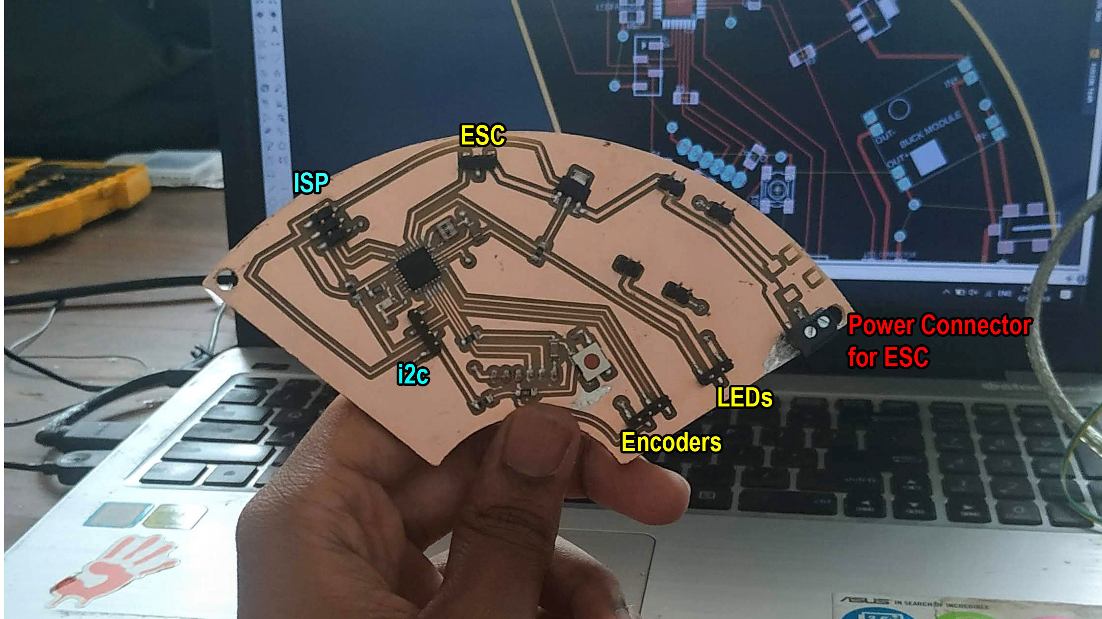
tinyESC is an ATtiny44 board that exists because of a bug. Once everything was integrated and I started programming, the LEDs behaved erratically. WS2812B are extremely fussy about timing, and sending LED data blocks; add the ESC PWM and the encoder interrupt on the same microcontroller and the timing falls apart. So motor control moved off the main loop entirely. The ATtiny44 does nothing but run the ESC, and the 328P turns it on and off with a digital line over the unused I2C pins.
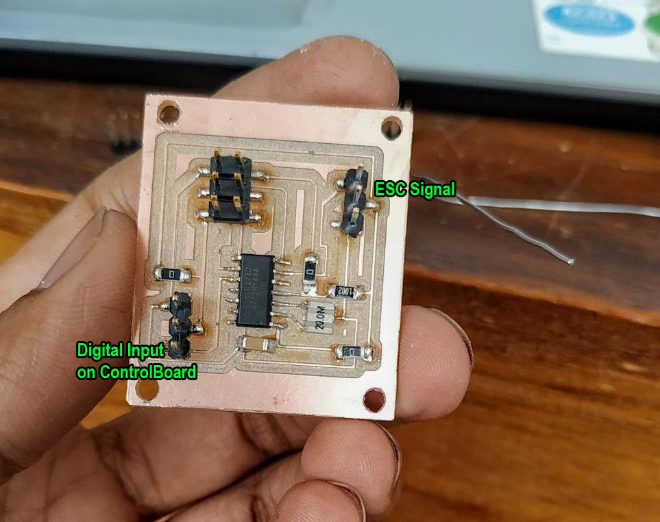
The 44E breakout is a breakout for the hall effect sensor with a 10k pullup between the output and 5V. Nothing clever, but it needed to sit in a printed mount at a fixed distance from the magnet.
Firmware
The constraint that shapes all of the code is that nothing may block.
delay() is essentially unusable here.
At 1100 RPM the arm turns about 18 times a second. The code divides each
revolution into 24 angular frames, so the LEDs have to be rewritten
roughly 440 times a second, which leaves about 2.27 milliseconds per
update. That turned out to be plenty for fourteen LEDs on a 20 MHz part,
but only because of two decisions: the LED library is
NeoPixelBus rather than FastLED,
because it can be driven non-blocking, and the encoder interrupt is
written in AVR C rather than going through Arduino’s attachInterrupt
handler. Compiled at -O2.
Two things were demonstrated on it: a poker face, and the Bangladeshi flag.
What worked and what didn’t
Everything worked except the arm material. 2mm acrylic is not stiff enough at 1100 RPM. It bends under load, and because the LEDs are no longer where the code thinks they are, the pixels trail. A high-speed photo of the arm mid-rotation shows the bend clearly.
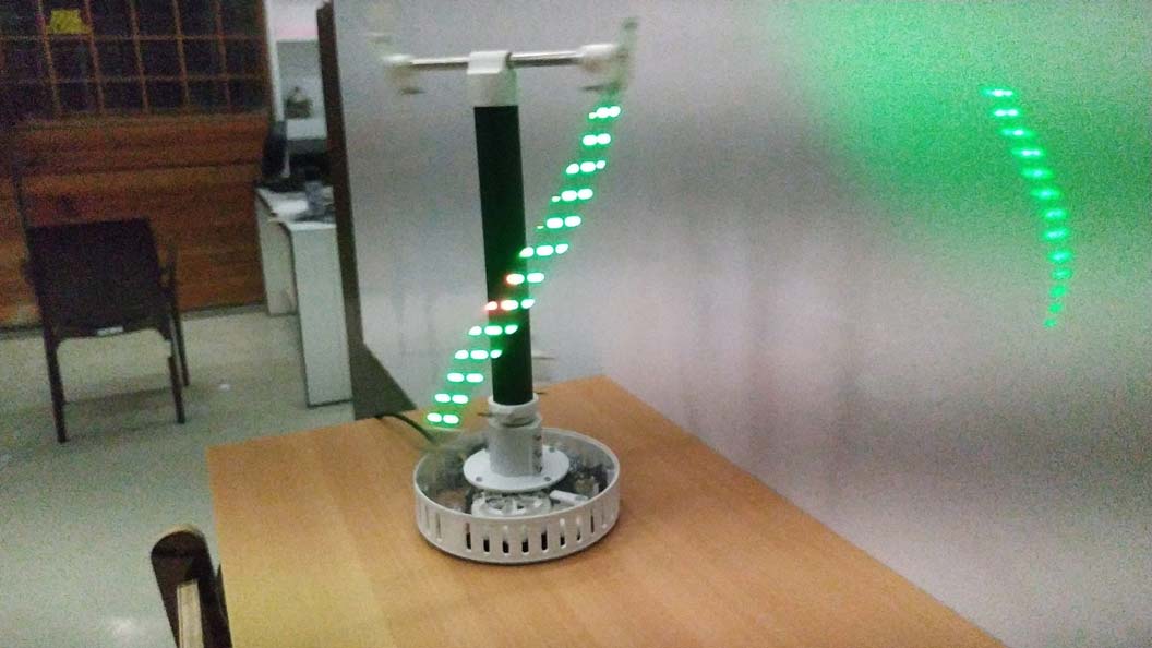
The fix is a stiffer arm, either a composite or a different section. That is the one open question left on the machine; everything else went through enough iterations to be settled.
Outcome
PixelFace was submitted and passed as the 2019 final project. It has not been rebuilt since. Bangladesh had no full fab lab at the time, so the follow-up work on the arm material never had a workshop to happen in.
The parts worth taking away are transferable: a home-made slip ring that passes clean addressable-LED data across a rotating joint, a way to fit a milled PCB into a CAD assembly, and the habit of pushing a time-hostile peripheral onto its own microcontroller instead of fighting it in one main loop. The last one showed up again years later in the Embryonic Shifts zoetrope, which is the same problem in a different shape: a strobe that has to fire in the same angular place every revolution.
All the CAD, board files, and code are in the project archive, and the full build log with every part broken out is on the project development page.