Embryonic Shifts
A large mechanical zoetrope for a STE(A)M installation on biology and identity — 72 sculpted objects in three stacked layers, frozen mid-rotation by a strobe that has to land in the same angular place every single revolution.
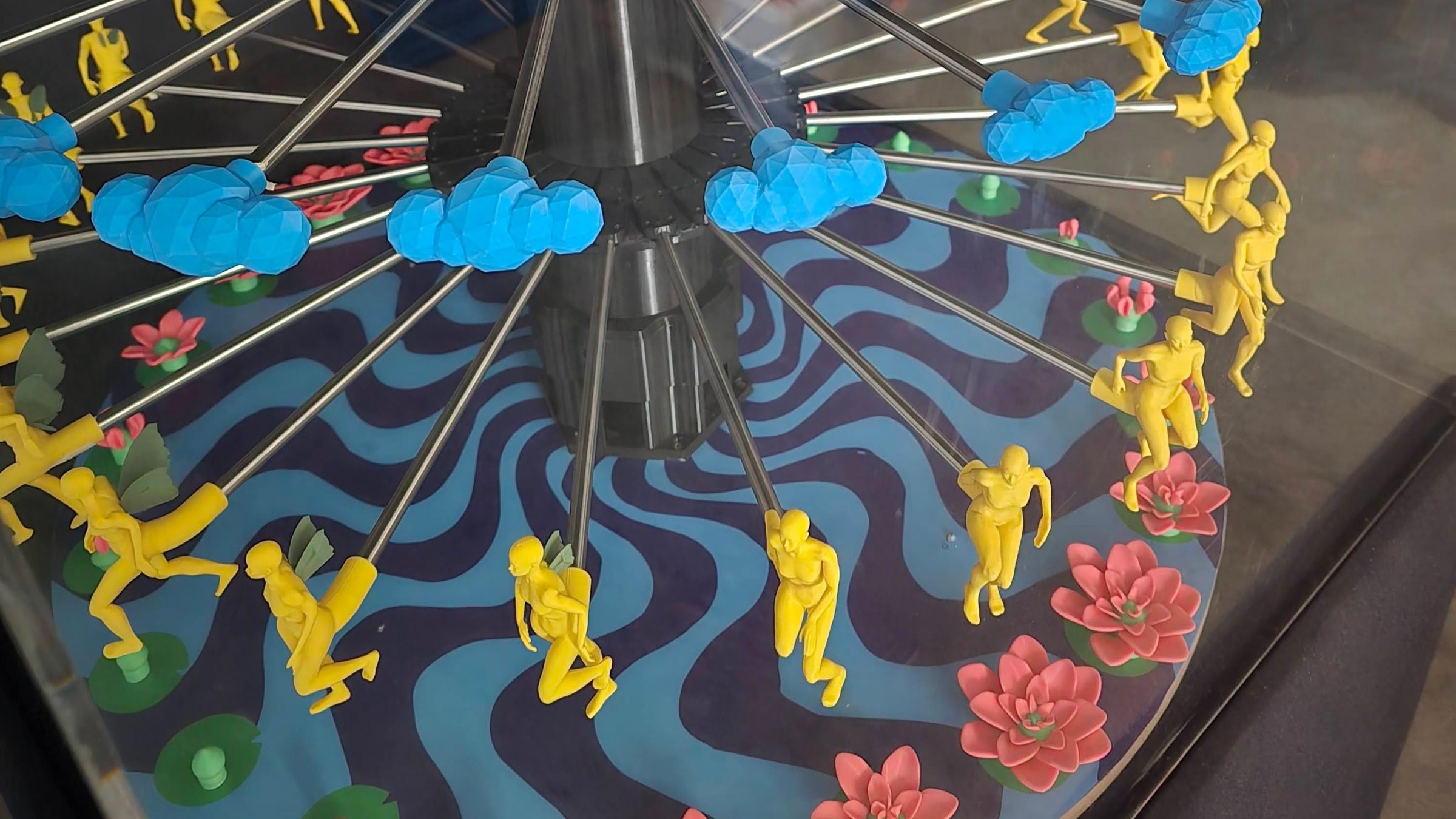
Embryonic Shifts (Rupantor) is a STE(A)M installation by Saiq’a Shabnam Chowdhury and me, produced by Ghorar Dim Studios and supported by the British Council through the WOW (Women of the World) Bangladesh 2026 programme. It was shown at SHALA Neighbourhood Art Space, Dhaka, 22–29 August 2026.
Saiq’a made the sculptures. I built the machine that animates them, and this page is that side of it — mechanism, strobe electronics, firmware and drawings. The firmware, drawings and build notes are on GitHub.
Filming a zoetrope honestly is its own problem. A camera at an arbitrary frame rate beats against the 24-frame cycle and produces a drift that nobody standing in the room ever sees, so the capture rate has to be matched to the platter. What is on the video is what the strobe is actually doing.
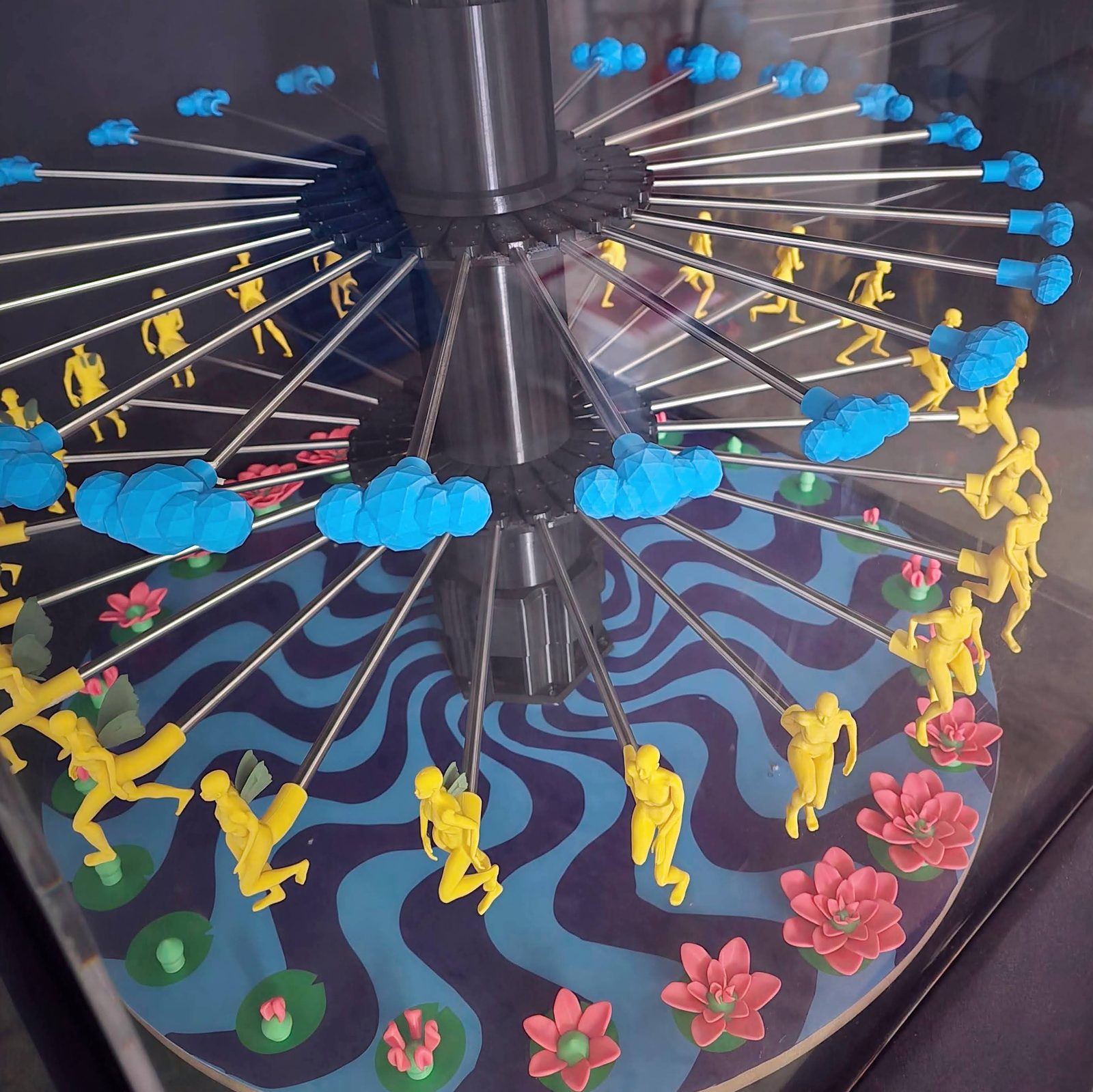
What you are looking at is a large mechanical zoetrope: an 843.6 mm platter turning inside a lit box, carrying 72 sculpted objects in three stacked layers of 24 — flowers on the platter itself, human forms on the middle tower ring, clouds on the top — with a strobe that fires once per figure so the eye assembles a single 24-frame animation loop instead of a ring of blurred objects. One animation, running simultaneously at three heights.
At full speed a figure arrives every 25 ms and the strobe answers with a 300 µs flash, so the room is dark 98.8% of the time. Everything a visitor sees, they are holding on their own retina.
Persistence of vision
Persistence of vision is the optical effect where the retina holds an image for roughly a tenth of a second after the light that made it is gone. Feed it rapid stills and they blend into continuous motion. It is the science under film, animation and the zoetrope alike.
It is also the reason the piece is a zoetrope rather than a screen. A screen would show you the animation; the zoetrope makes you complete it — and that only works if every flash lands in the same angular place on every single revolution. The rest of this page is about making that true.
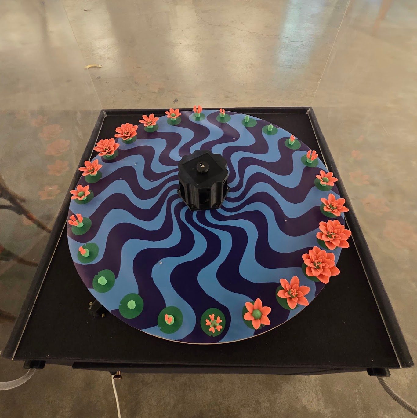
Mechanical assembly
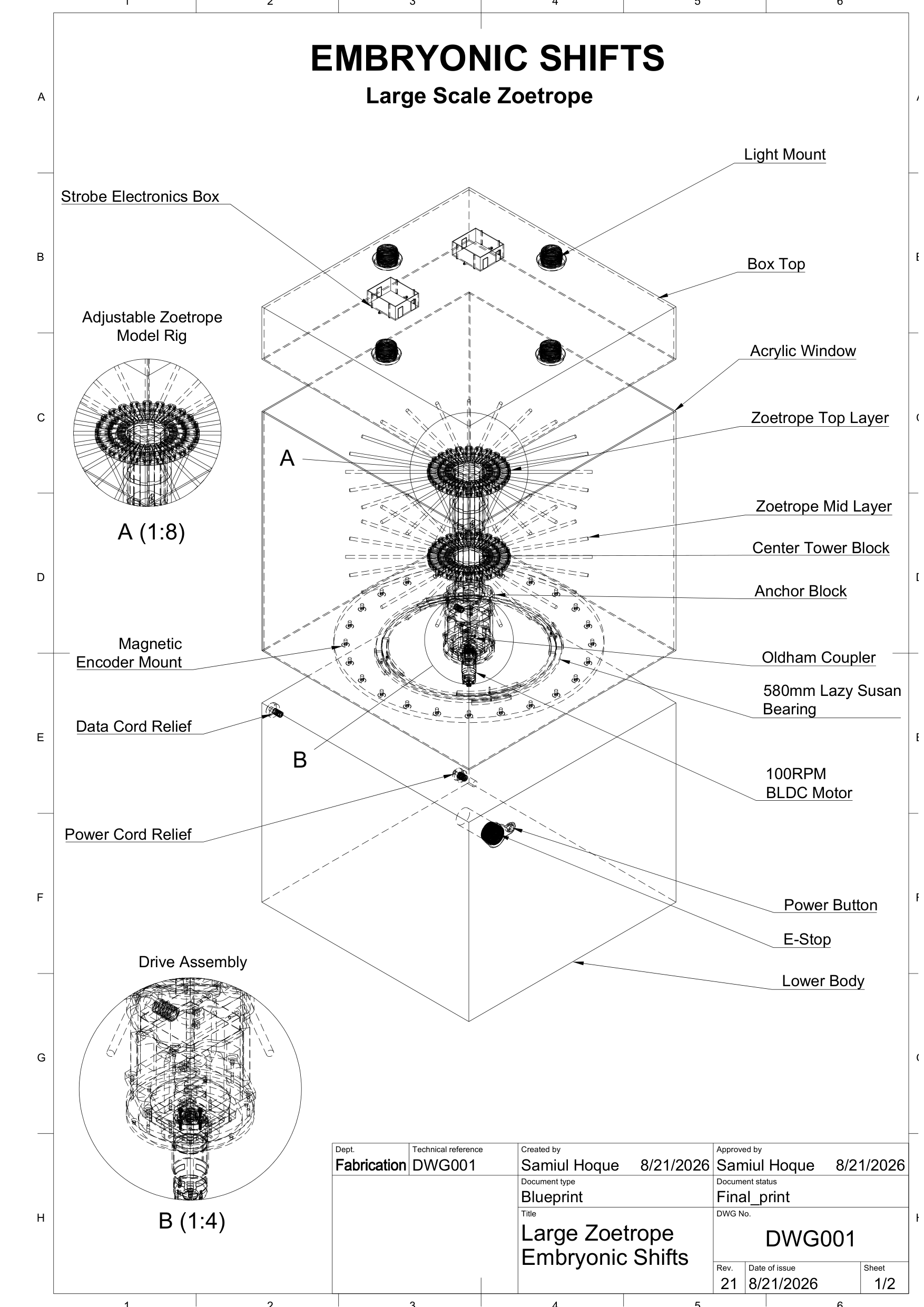
The general arrangement: box top carrying the light mounts and the strobe electronics, acrylic window, the two zoetrope layers on the centre tower, anchor block, Oldham coupler, the 580 mm lazy susan bearing, the BLDC, and the magnet-ring mount that carries the hall sensor. Power button, E-stop and both cord reliefs sit on the lower body.
| Platter | 843.6 mm, on a 580 mm lazy susan bearing |
| Objects | 72 in three layers of 24 — flowers on the platter, humans and clouds on two modular tower rings of 24 radial spokes each, radius and height both adjustable |
| Rig rings | 24× 9.6 mm OD stainless pipe at 320 mm, 4× M3×10 hex per ring |
| Drive | 100 rpm BLDC, 24 V @ 1.65 A, own controller, custom Oldham coupling to the driven shaft |
| Index | 24 neodymium magnets at ~410 mm radius, one dead centre under each animation frame |
| Frame pitch | 15.00° — 107.3 mm of arc at the magnets |
| Speed | 30–100 rpm → 12–40 fps |
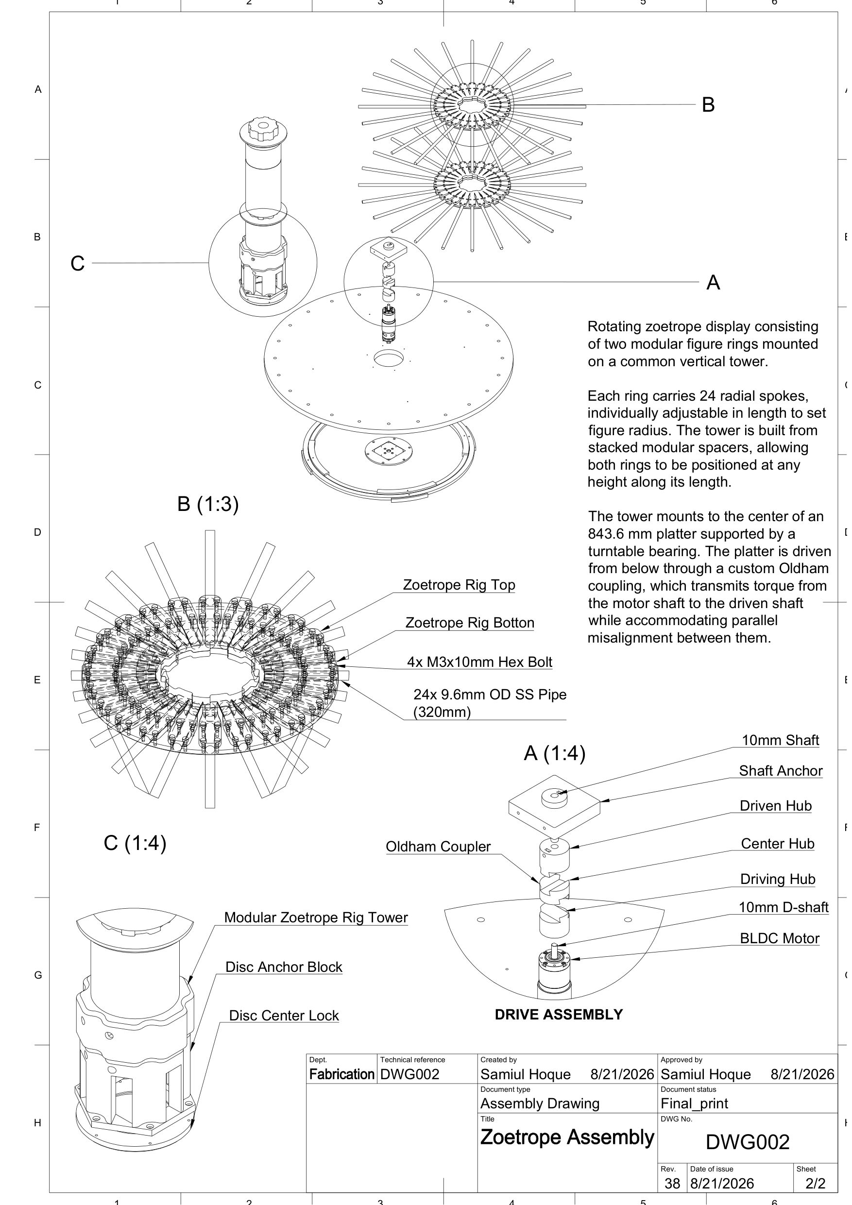
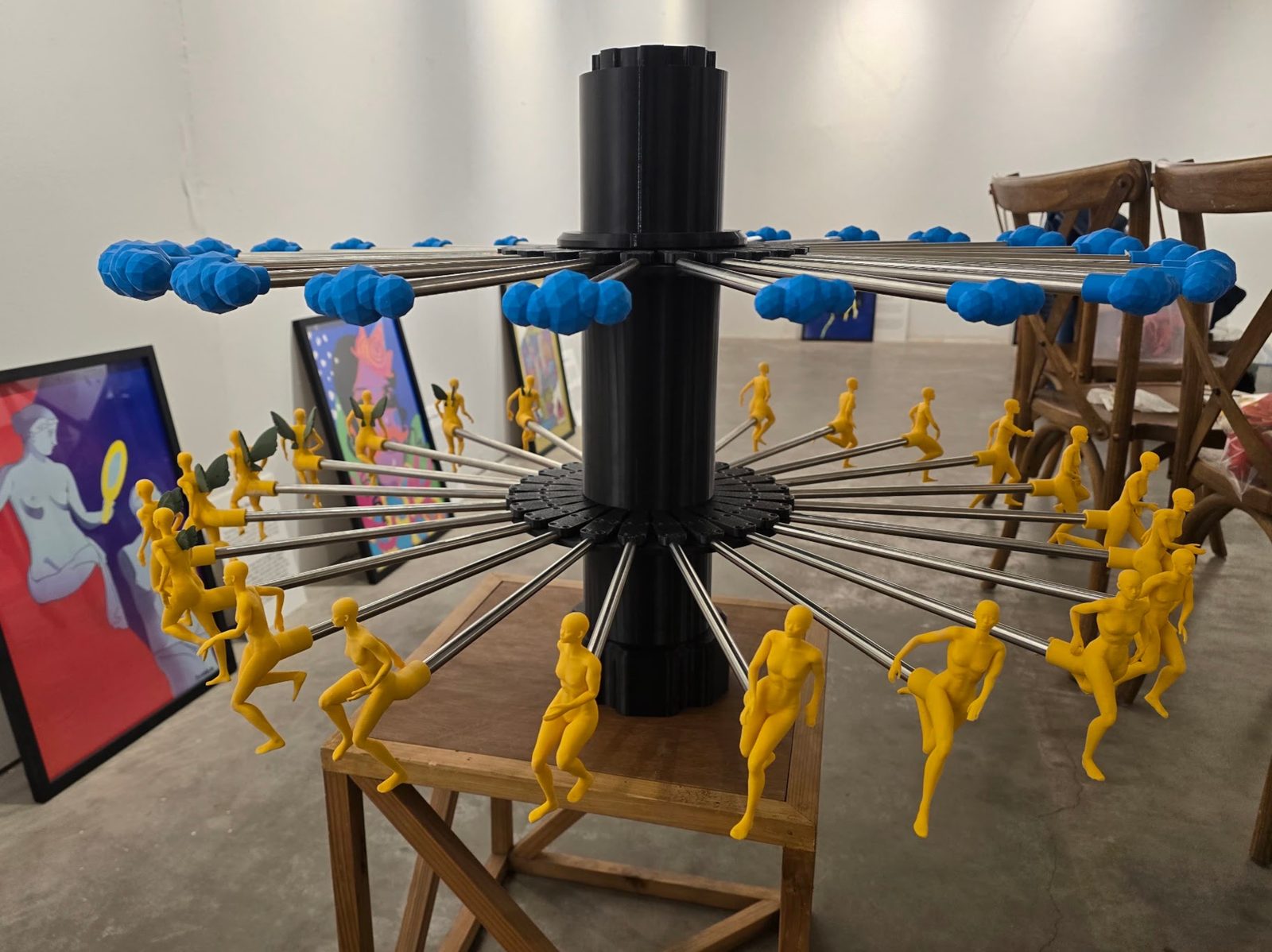
The bottom layer sits directly on the platter and simply turns with it. The other two ride the same vertical tower, stacked out of modular spacers, and each of the 24 radial spokes on each ring is individually adjustable in length — which is what lets the three layers be aligned into one frame vertically as well as angularly. That was a deliberate concession to the fact that the sculptures were still being made while the mechanism was being built — figure radius and ring height stayed variables until quite late, and the rig had to absorb that without a redesign.
Detail A on the drawing is the drive train exploded: 10 mm shaft, shaft anchor, driven hub, centre hub, driving hub, 10 mm D-shaft, BLDC. That is a custom Oldham coupling — it lets the motor sit slightly off the driven shaft’s axis without fighting it, because parallel misalignment gets absorbed by the sliding centre hub rather than loaded into the lazy susan bearing. On a platter this size, “just align it properly” is not a maintainable answer, because the piece has to be struck, transported and re-hung.
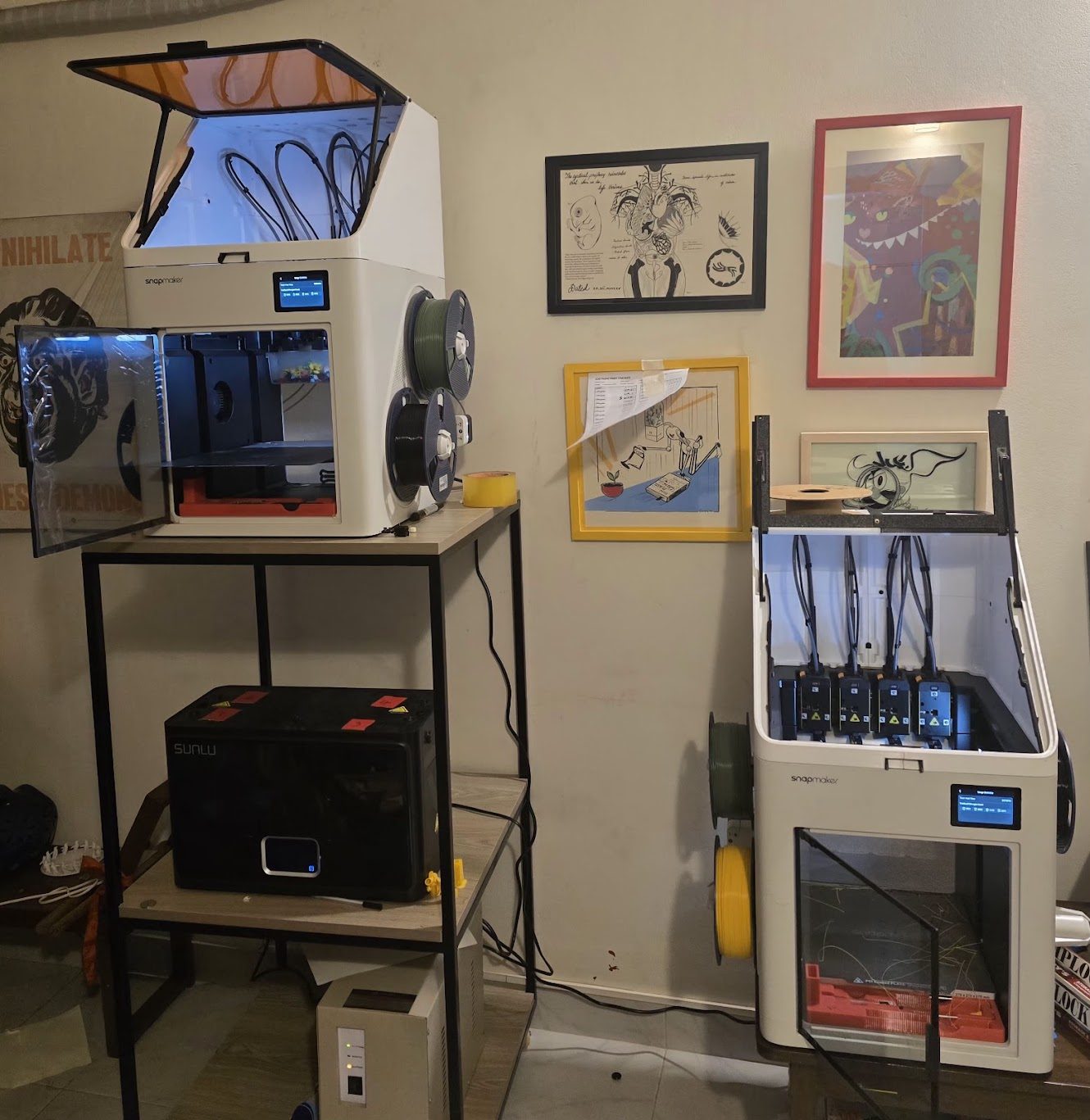
Everything you can see was printed here. The 72 objects, the tower, the hubs, the ring spokes, the light mounts, the sensor bracket and both driver board enclosures came off two Snapmaker U1s, fed from a Sunlu S4 Pro filament dryer, for a total of about 1700 hours of print time across the project. The machines were pre-ordered for this piece and arrived as the first two U1 units in Bangladesh.
That capacity is the other reason the rig is built out of modular, individually adjustable parts. When the sculptures are still changing, a part you can reprint overnight is worth more than a part that is right the first time.
Index timing and error correction
This is the part the whole exhibit lives or dies on, and it is the part the first build got wrong.
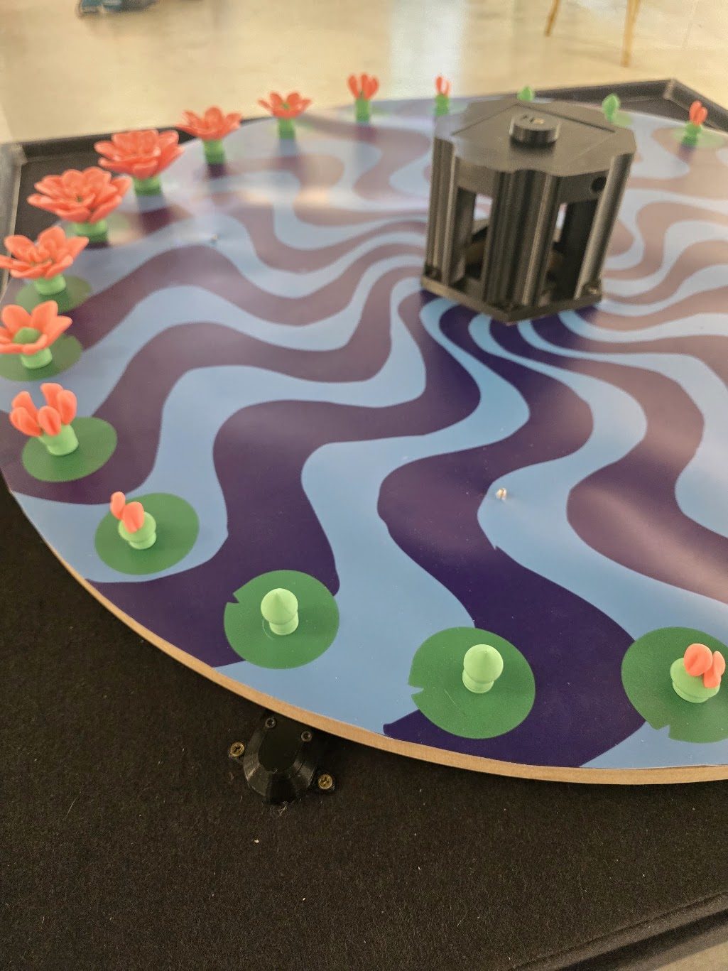
A fixed A3144 hall sensor on the deck reads the 24 magnets riding under the platter. The tempting move — and the one the previous build made — is to treat each magnet as the authority on where its own figure is, and fire the strobe straight off its leading edge. One magnet per figure, one flash per magnet, no frames-per-revolution multiplier anywhere in the code. It is clean, and it produces an image that will not sit still.
The reason is that magnet k does not assert at 15k°. It asserts at 15k° + eₖ, where eₖ rolls up glue placement, magnet strength, air gap and platter wobble — everything that shifts where the sensor’s field crosses its operate threshold. eₖ is different for every magnet and, far more importantly, it is repeatable for every magnet.
So firing off the edge paints each figure a couple of millimetres from where the last one was painted, in the same pattern every revolution. That is not noise, which the eye would average away. It is a fixed 24-step wobble locked to the drum, and it reads as an image that refuses to freeze.
The scale is unforgiving:
| One degree of rotation | 7.2 mm of movement out at the figures |
| A third of a degree of placement error | ~2 mm of visible image swim |
| An 8 mm magnet | ~7.5% of a frame — the dwell to expect |
| Rim speed at 100 rpm | 4.42 m/s → magnet in front of the sensor for 1.8 ms |
| A 300 µs flash at 100 rpm | 1.3 mm of smear |
Two millimetres of swim is the difference between a sculpture that breathes and a shelf of blurry objects.
The fix is to use the magnets for the one thing they are genuinely good at: saying when a revolution began and how fast the platter is turning. Averaged over a full revolution, eₖ cancels exactly — 24 pulses lands you back on the magnet you started from, so the revolution period is correct no matter how badly the individual magnets are placed. The ideal 15.00° frame grid is derived from that rate, and a learned per-magnet offset drags each flash off its own magnet and onto the grid:
a[k]  = k * (rev / 24) + err[k]     when magnet k actually arrived
corr  = -err[k]                     applied to that magnet's flash delay
The correction table is recomputed ten times a second from loop context — that is where the 64-bit division and the floating point are allowed to live. The interrupt handler does one signed add with the result and nothing else. It needs four consecutive clean revolutions before it applies, and any missed or rejected edge restarts the count.
The firmware keeps the old, uncorrected behaviour as a selectable mode
(timed) alongside the corrected one (locked), specifically so the fix can
be seen rather than taken on trust. Switch between them with the piece
running: timed visibly wobbles, locked does not.
Dwell — how long each magnet holds the sensor asserted — is no longer used to time the flash at all, since the correction table absorbs the leading-edge offset along with everything else. It is still measured and reported per magnet, because it is the single best readout of a magnet that is weak, too far away, or fitted the wrong way round. An A3144 is unipolar and only answers one pole, so a slot that shows intervals but no dwell is a reversed magnet — a five-second diagnosis instead of an afternoon.
Strobe electronics
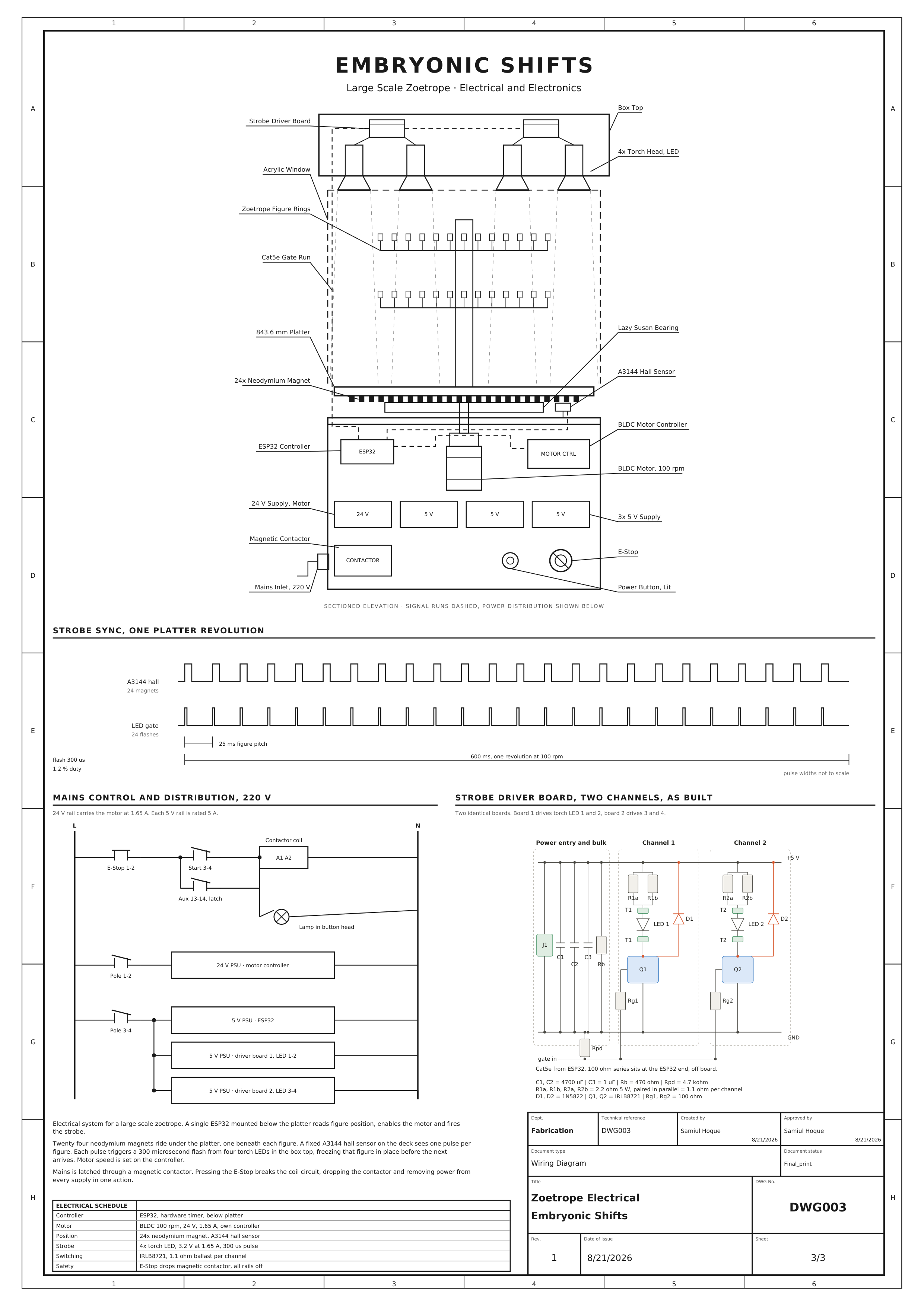
Sectioned elevation with the signal runs dashed, plus the strobe sync timing against one platter revolution, the 220 V mains ladder, and the driver board as built.
| Controller | MH-ET LIVE ESP32 MiniKit (classic ESP32-D0WD-V3), below the platter |
| Index | A3144 hall sensor on GPIO27, INPUT_PULLUP, open-drain active-low |
| Strobe gates | GPIO25 → driver board 1 (LEDs 1–2), GPIO26 → driver board 2 (LEDs 3–4), active high |
| Emitters | 4× torch-head LED in the box top, 3.2 V @ 1.65 A |
| Switching | IRLB8721 low-side per channel, 1.1 Ω ballast (2× 2.2 Ω 5 W in parallel), 1N5822 flyback, 4700 µF + 1 µF bulk, 4.7 k gate pulldown |
| Flash | 300 µs design pulse, 1.2% duty at 100 rpm, 5 ms absolute ceiling |
| Supplies | 24 V motor rail; 3× 5 V — ESP32, driver board 1, driver board 2 |
| Mains | 220 V latched through a magnetic contactor; E-stop drops the coil and every rail with it |
| Signal runs | one Cat5e per driver board — signal on one conductor of a twisted pair, ground on its partner |
| Network | Wi-Fi, mDNS hall.local — web dashboard, telnet console, OTA |
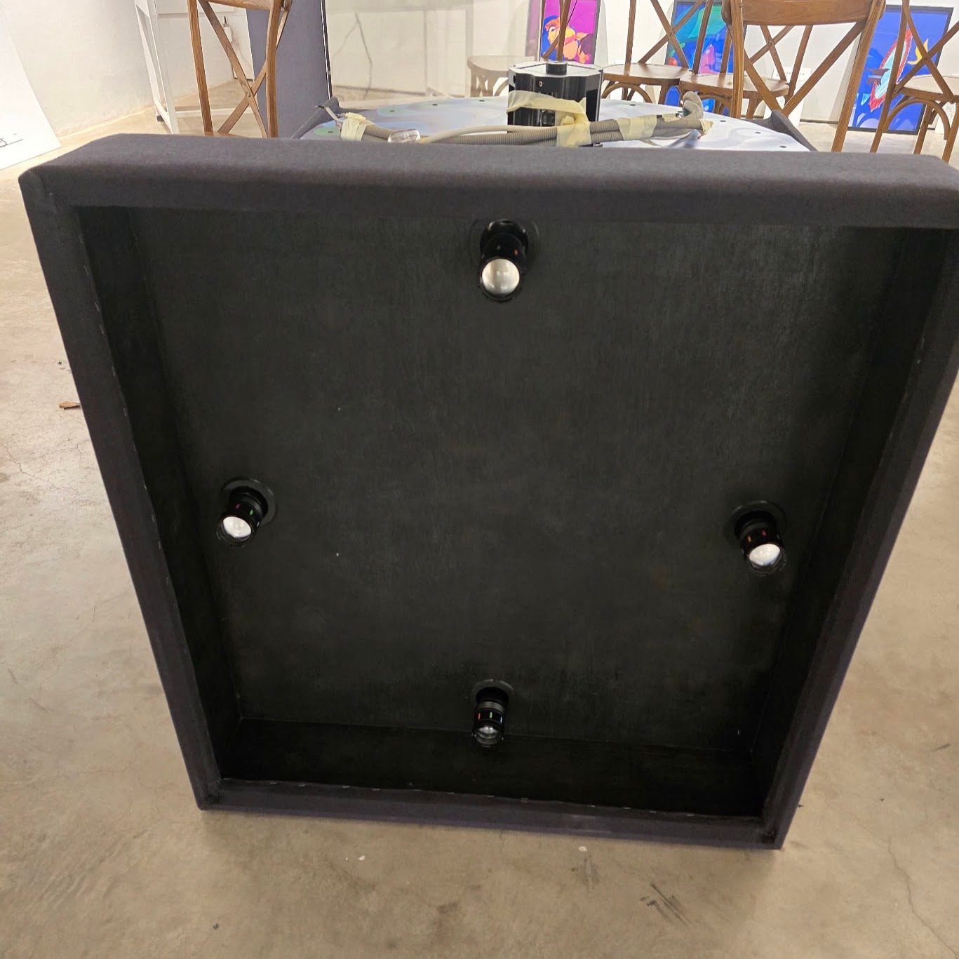
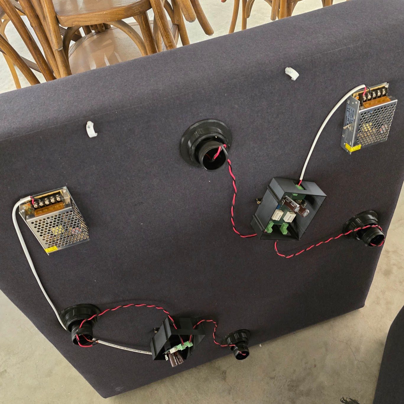
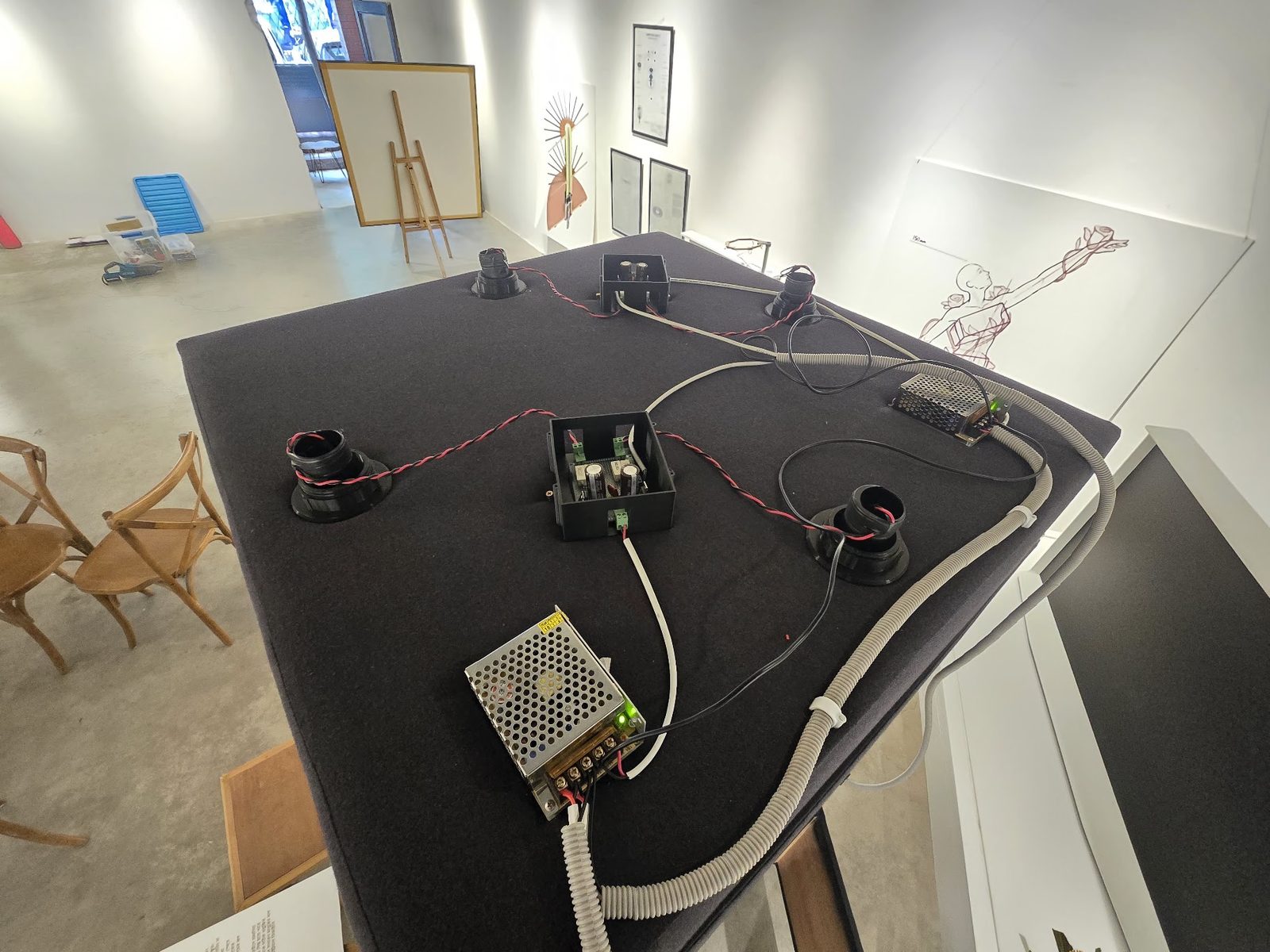
The four emitters in the box top, and the same panel from the other side: two 5 V supplies, the two driver boards in printed enclosures, and one twisted pair out to each light. Boards 1 and 2 each take two lights, which is why the firmware treats the strobe as two channels that must rise together.
Driver board
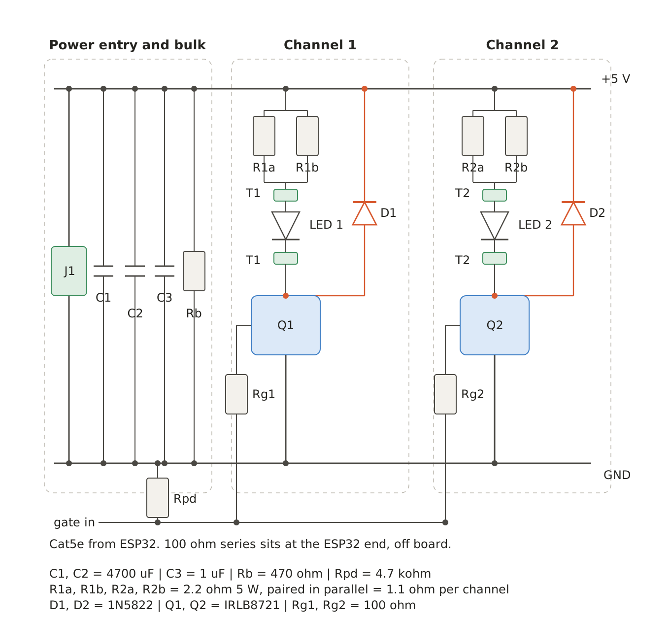
There is no cleverness in it, and that is the point — the timing all lives in the firmware, so the board’s only job is to put a hard-edged 1.65 A through a LED when the gate says so and to be uninteresting the rest of the time. Two identical channels, one MOSFET each, everything shared upstream.
Three parts of it are sized rather than chosen:
- The ballast is 2× 2.2 Ω 5 W in parallel, not one resistor. A torch head at 3.2 V and 1.65 A off a 5 V rail needs about 1.1 Ω to drop the difference, and while the pulse is on that resistor is dissipating 3 W. At 1.2% duty it averages under 40 mW and never gets warm — but it has to survive the instantaneous power, not the average, which is what the two 5 W parts are for. They are the four white blocks in the photo below.
- The bulk capacitors are what the flash actually comes out of. Each board
pulls 3.3 A for 300 µs across its two channels — about 1 mC — and 9400 µF
sags roughly 0.1 V delivering it. The energy is already sitting on the
board when the gate opens, so the flash does not have to travel up the
supply run to get there.
Rbbleeds the bank down when the contactor drops. - The 100 Ω resistors on the board are gate damping, one per MOSFET. They are not the same part as the 100 Ω in the next paragraph, which sits at the other end of the cable and does a different job.
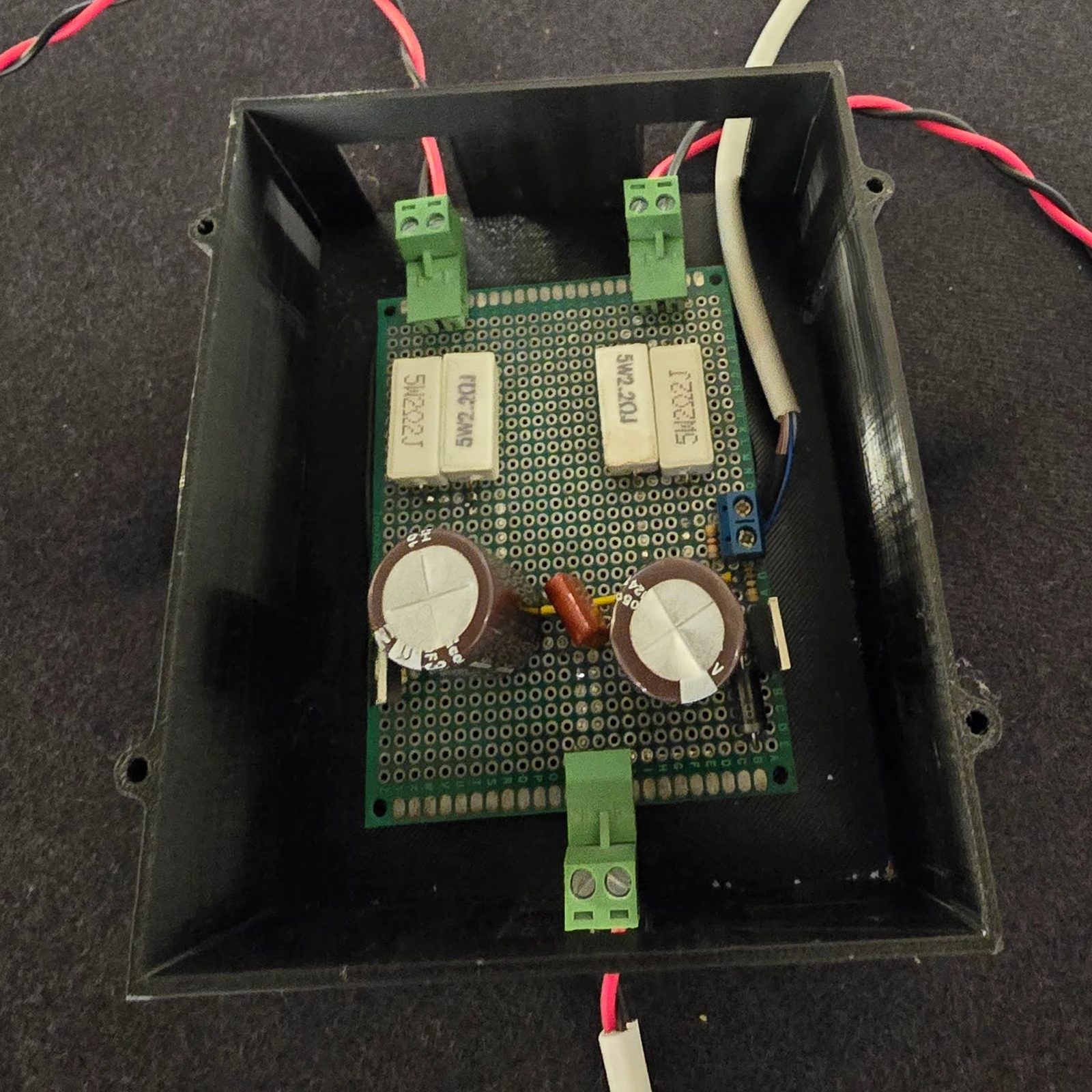
Two details in that table are doing more work than they look like they are.
The pull-down is at the far end, the series resistor is at the near end. The 100 Ω on the signal line sits at the ESP32 pin, off board; the 4.7 k gate pulldown sits at the driver board where the cable lands. That asymmetry means an unplugged or cut Cat5e run leaves that board dark rather than floating — and so does an ESP32 that has not finished booting. On a piece that faces the public, the failure mode of a damaged cable should be “one side of the box goes out”, not “one side of the box comes on and stays on”.
Both strobe pins are below GPIO32, which means they can be raised by a
single GPIO.out_w1ts register write with genuinely simultaneous rising
edges. Nothing in the firmware is allowed to turn them on separately — two
digitalWrite() calls would stagger the edges by microseconds and smear the
composite image across the box. Only the falling edges stagger, and only when
the two boards are trimmed to different flash widths, which the timer handles
as a third phase.
The only DC reference between the box-top boards and the controller under the platter is the Cat5e ground. If phantom index triggers ever show up, that is the path to suspect first — not the hall sensor.
Firmware: interrupt-context constraints
The exhibition build crash-looped for an afternoon over two rules, so they are written at the top of the handover doc now.
No floating point in an ISR. Ever. ESP-IDF does not support the FPU
inside an interrupt handler — the Xtensa FPU is lazily context-switched and
its registers are not saved for ISRs, so touching it corrupts the coprocessor
state of whichever task happened to be interrupted. The panic does not point
anywhere near your code: it lands in _xt_lowint1 with LoadProhibited,
blamed on IDLE1 (whose stack the ISR was borrowing), with a corrupted
backtrace. This is why the phase value exists twice — a float for the maths
in loop context, and an integer 0..65535 mirror for the interrupt to use.
No flash-resident code in an ISR either. The flash cache is disabled
during Wi-Fi PHY calls and NVS writes, and an interrupt that reaches into
flash during that window faults identically. Which rules out digitalRead(),
micros(), attachInterrupt() and the whole timerAlarm* family — replaced
with direct register reads, esp_timer_get_time(), and
gpio_install_isr_service(ESP_INTR_FLAG_IRAM).
Neither rule is checkable by reading the code, so the handover doc carries the
nm/objdump commands that verify it against the built binary: every
ISR-path symbol must land in IRAM at 0x4008xxxx, every call target out of
that region must too, and there must be zero floating-point instructions in
the range.
One more trap is worth writing down, because it fails silently.
timerBegin() takes an index into a table in esp32-hal-timer.c that is not
in the order anyone would guess:
static hw_timer_t timer_dev[4] = { {0,0}, {1,0}, {0,1}, {1,1} }; // {group, num}So timerBegin(1, ...) is group 1 timer 0 — TIMERG1.hw_timer[0], not
TIMERG0.hw_timer[1]. Get that wrong and you are writing the alarm registers
of an unrelated timer. Nothing errors; the strobe simply never fires.
Index noise gate. The gate lines run several feet past a BLDC, so an induced glitch on the index input is a live risk rather than a theoretical one. On top of a 200 µs debounce, any leading edge arriving more than 30% early against the running average is dropped whole — no frame advance, no flash — and the last-good-edge timestamp is left alone so the next real magnet is still measured correctly. Long intervals are deliberately not gated: those are either a genuinely missed magnet or the drum slowing down, and both are handled by the gap analysis instead.
Operating it. Serial or telnet hall.local, both accepting the same
keys, plus a web dashboard on the same box. Bring-up is a fixed order: t
for a strobe self-test with the motor off, 1 for one flash per revolution,
b and turn the platter by hand, m to confirm all 24 magnets read an
interval and a dwell, then ramp the motor and c until calibration reports
APPLIED.
Safety systems
40 Hz sits inside the flicker band associated with photosensitive seizures, on a piece that faces the public in a dark room. Visitors sensitive to flicker are told before they enter. Beyond that there are two independent layers, and neither is a setting anyone can change on the night.
In hardware: mains is latched through a magnetic contactor. Pressing the E-stop breaks the coil circuit and drops power to every supply in one action — motor, controller and both driver boards together.
In firmware:
- One gate for the whole output.
fireAt()is the only function in any mode that can raise a pin. Both ceilings — 5 ms absolute, and 90% of frame time — are applied inside it, so a bug anywhere in the phase, drift or calibration maths can mistime a pulse but cannot lengthen one. - Fail dark. Kill switch, lost index, overrun, unexpected timer state and
OTA all drive both pins low.
failDark()is the first statement insetup(), before serial or Wi-Fi, so the gates are claimed and parked low as early as the chip can manage. - No free-running. Flashes only ever come from a real index edge. The correction table shifts a flash within its frame; it can never generate one. If the pulses stop, the output goes dark within 250 ms.
- Rate cannot be swept. One flash per index pulse, full stop. Nothing multiplies or divides it except a single discrete bring-up divider.
- Stuck-output backstop. Anything held high for more than 8 ms is forced low and counted as a fault.
When a ceiling bites, the pulse narrows — which from the floor looks like the
boards dimming for no reason. So it is reported rather than silent: a console
line on the transition, and a red clamped label on the dashboard.
Installation
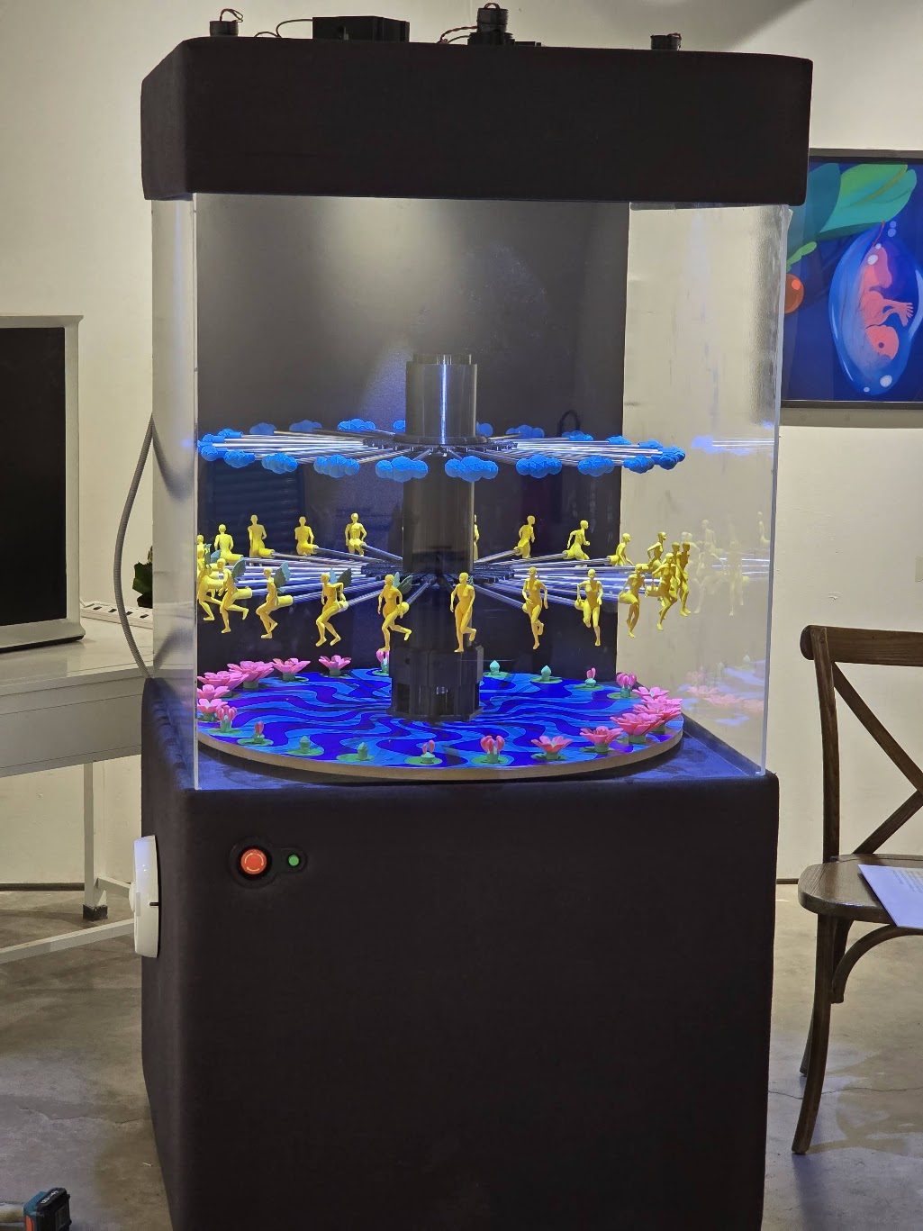
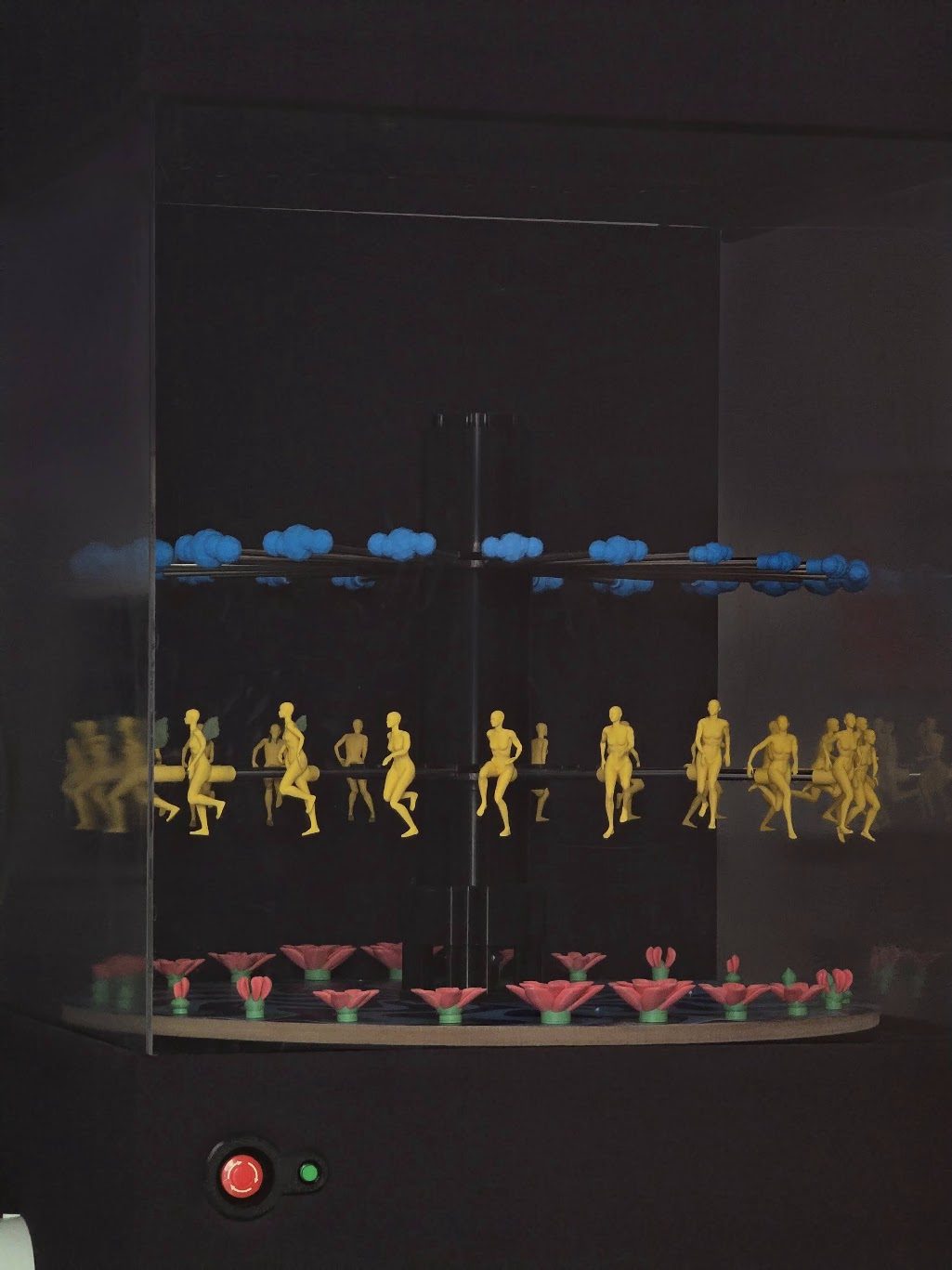
The piece as it stood at SHALA: the mechanism and every supply inside the plinth, the animation inside the vitrine, and nothing on the outside but a power button and an E-stop. With the room dark and the platter stopped, the three layers separate back into three bands — which is what a visitor sees for the half-second before it starts turning.

Acknowledgements
Embryonic Shifts (Rupantor) is by Saiq’a Shabnam Chowdhury and Samiul Hoque, produced by Ghorar Dim Studios. My half of it was making the work run for eight hours a day for a week without being touched.
The work also didn’t start in the studio: its development ran through intensive community engagement sessions with young people in Korail, integrating local voices and lived experience into the design phase.
Supported by the British Council through the WOW (Women of the World) Bangladesh 2026 programme, which backs female artists driving cultural dialogue.
Very special thanks to PARAA, MACHAN, SHALA Neighbourhood Art Space and ALOKI for making the show happen.
In the press
- The Business Standard
- The Daily Star