Lumo / Elektra — vehicle CAN bus reader
Two-revision vehicle CAN bus reader built at TeroLabs — v1 a Raspberry Pi HAT for prototyping, v2 a standalone BLE device for in-car deployment.
Context
At TeroLabs we kept ending up in projects that needed to read data off a vehicle. The OBD-II dongles on the market were either too expensive, too proprietary, or both. So we built our own hardware.
Internally the project went by two names — Lumo and Elektra — depending on whichever branding the studio was running with at the time. Two distinct hardware revisions, different form factors, same goal.
v1 — CAN bus HAT (Raspberry Pi testbed)
v1 was a CAN bus HAT that stacked on top of a Raspberry Pi. It had an ESP32 onboard and carried a DB9 connector that plugged into the vehicle’s CAN bus port. The Pi HAT form factor was deliberate — it let us run tests locally on the Pi during development, which sped up the feedback loop considerably. The point wasn’t to ship v1 — it was to prove out the pipeline: confirm we could read frames reliably, experiment with decode logic, and validate the approach before committing to a standalone design.
This is the revision whose design files I keep on my own GitHub (samiul-hoque/CAN-BUS-HAT_lumo). It is the CAN bus HAT, not the direct-plug OBD device — that’s v2.
v2 — Standalone device
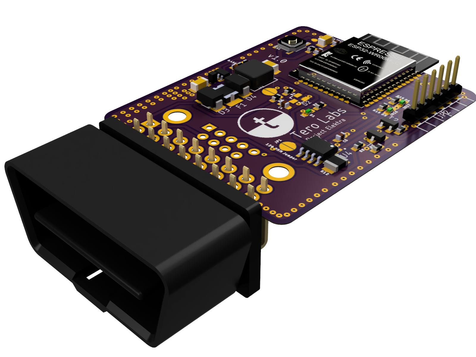
v2 also had an ESP32 onboard but dropped the Pi dependency entirely. It was a self-contained board designed for in-car deployment. The connector was configurable at assembly time — either a CAN bus connector or a DB9 could be soldered on depending on the target vehicle. For connectivity it paired with a phone app over BLE, which relayed data up to our server.
The enclosure was designed in Fusion 360: snap-fit, printable on a hobby printer, sized to sit flat under a dashboard without getting in the way.
Where it ended up
The v2 hardware became the sensor layer for a driver-behaviour analysis pipeline: read CAN frames, decode the parameters that mattered (speed, throttle, brake, RPM, steering inputs where available), and relay the stream through the phone app to the analytics backend. The interesting work downstream wasn’t mine, but every datapoint that fed it came through this board.
Where the design files live
The two revisions live in two different repositories, and they are not mirrors of each other — each holds a different board.
- v1, the CAN bus HAT, is the one I keep publicly on my own GitHub: samiul-hoque/CAN-BUS-HAT_lumo. Schematic, board, enclosure, and renders are all there.
- v2, the standalone OBD device, lives in the TeroLabs repo Tero-Labs/elektra-OBD-device_0.1. I no longer work there and no longer have access to that repository, so I can’t maintain it or guarantee it stays online. The v2 photos and renders on this page are mine; the v2 source files are not in my hands.
If you’re trying to do something similar and want the v1 design files, get in touch.