Networking & Communications
Design and build a wired or wireless network connecting at least two nodes.
Assignment
Individual Assignment:
Design, build, and connect wired or wireless node(s) with network or bus addresses
Group Work
Send a message between two projects
What I made this Week
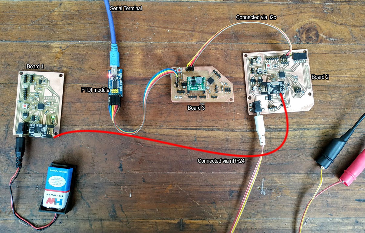
Context
Embedded communication is the process of sending information between two MCUs or from one circuit to other. For a communication to happen there needs to be a transmitter and a receiver. Communication may be in one direction or in both directions, there are different classifications according to this, but the basic classification is Synchronous and Asynchronous communication.
Synchronous
Sender and receiver use the same clock signal. An example is i2c and SPI, where a clock line (SCL or SCK) is shared between the sender and receiver.
Asynchronous:
Sender provides a synchronization signal to the receiver before starting the transfer of each message. And example of this is Serial Communication, where there is no shared clock, which is why we needed to fix the baude rate for boards to communicate with eachother.
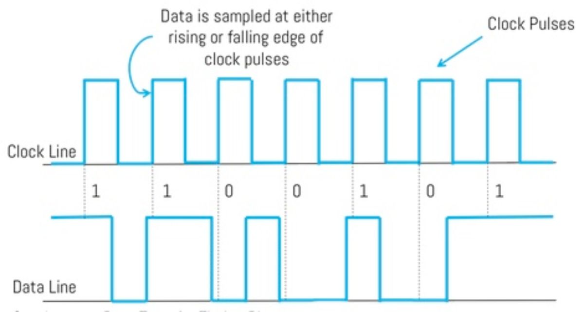
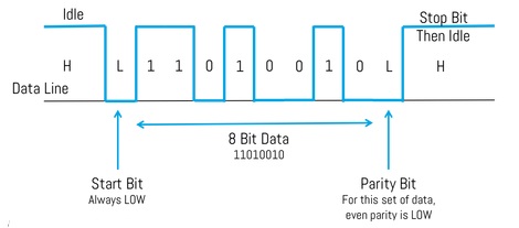
Some of my previous Networking & Communiction projects
Networking is definitely not my forte, but it has been quite a journey learning all about it through the years. Here are some of my most notable networking projects before I get to this weeks assignment.
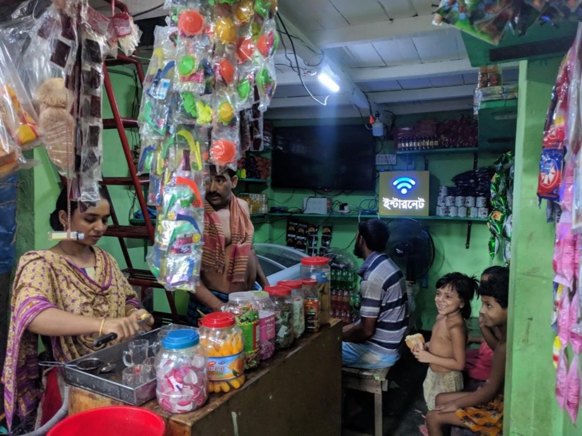
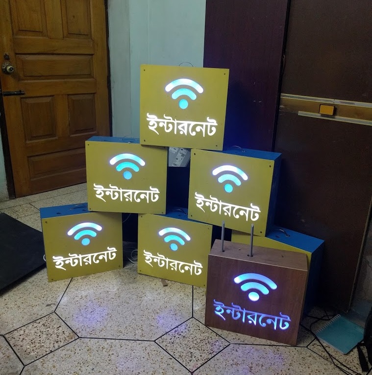
Community Internet Router
All the details about my communitiy internet Router can be found here. I am working on a cheap mikrotik routerboard and running a custom openWRT firmware on it. The Authentication server is based on Diameter, the captive portal is based on CoovaChilli. We went to SANOG32 to present our idea and right now 5 nodes has been running for about 6 months as our pilot project.
A key point in our network deployment is the dependence on the local Internet Exchanges. Since most of our users only use cached data services like Facebook and Youtube, the latency we have been able to provide has been better than any Telcos or ISPs operating in that area.

The Basic Selling point is Seamless internet experience for 3 hours in 5tk, that’s 0.060 USD
Milestones Reached:
- 900 unique users reached, on our 5 nodes. Considering unique mac IDs.
- Average consumption of data is 684 MB download, 27 MB upload.
- Total Data consumed after setting up the four nodes is 5088 GB.
- Assuming the minimum price of 1 GB data from the telcos as 100tk, that’s about 610,560 BDT of data consumed by the users.
- We sold about 7000 5tk unlimited tokens, which is about 17 times cheaper than the average telcos and 94% of the price was slashed.
Weather Balloon Tracking
Back in 2015, I had the privilige to work for a weather balloon launch. I made a GPS tracking system for a weather balloon using a Radiometrix NTX-2b, a 433MHz RF transmitter. The mainboard was based on a raspberry Pi, the GPS device used was a Ublox-Neo 6. The onboard camera later recovered gave us some amazing footage. The vertical distance traversed was 32450.1 meters and the total displacement was 68.8km. The Communication device was able to keep track of it during the full journey while surviving extreme temperatures from - 25.312 Degree Centigrade to 40 Degrees.All the details about this project can be found here.

The Recieving Yagi Antenna was made using locally available materials such as copper rods and PVC sheets. Here are some of the notable data from the launch:
- Total Flight Time : 3 Hours 26 Minutes 41 seconds.
- Total ascend Time: 2 Hours 07 minutes 12 seconds.
- Total decent Time : 1 hours 19 minutes 29 seconds.
- Lateral Displacement : 68.8km
- Lowest recorded outside Temperature: - 25.312 Degree Centigrade
- Highest recorded Altitude : 32450.1 meters
Onboard Camera Recording:

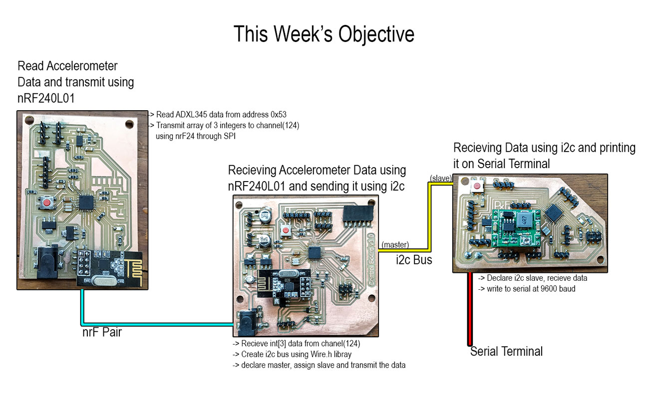
This week’s Objective
For this week, I wanted to challenge myself with a networking project. I wanted to use all the networking protocols available to me in one assignment. So I’ll be using the following protocols;
- SPI
- i2c
- Serial
First Objective:
Interface the ADXL345, an i2c accelerometer which works on 3.3v, transfer the accelerometer data using nRF24L01+ modules which use SPI communication. I’ll have to design a board that works on 3.3v which will be convinient to work with these components.
Second Objective:
Recieve the accelerometer data using another nRF24L01+ module, and send it to another board using i2c.
Third Objective:
Recieve Data using i2c, and writing it on Serial so I can see it on the Serial Monitor.
The Board’s I’ll be Using
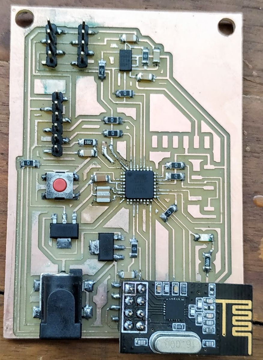
Features:
- Atmega328p 8MHz running on 3.3v
- Onboard Devices: nRF24L01+, ADXL345
- Hardware i2c and Serial pinouts
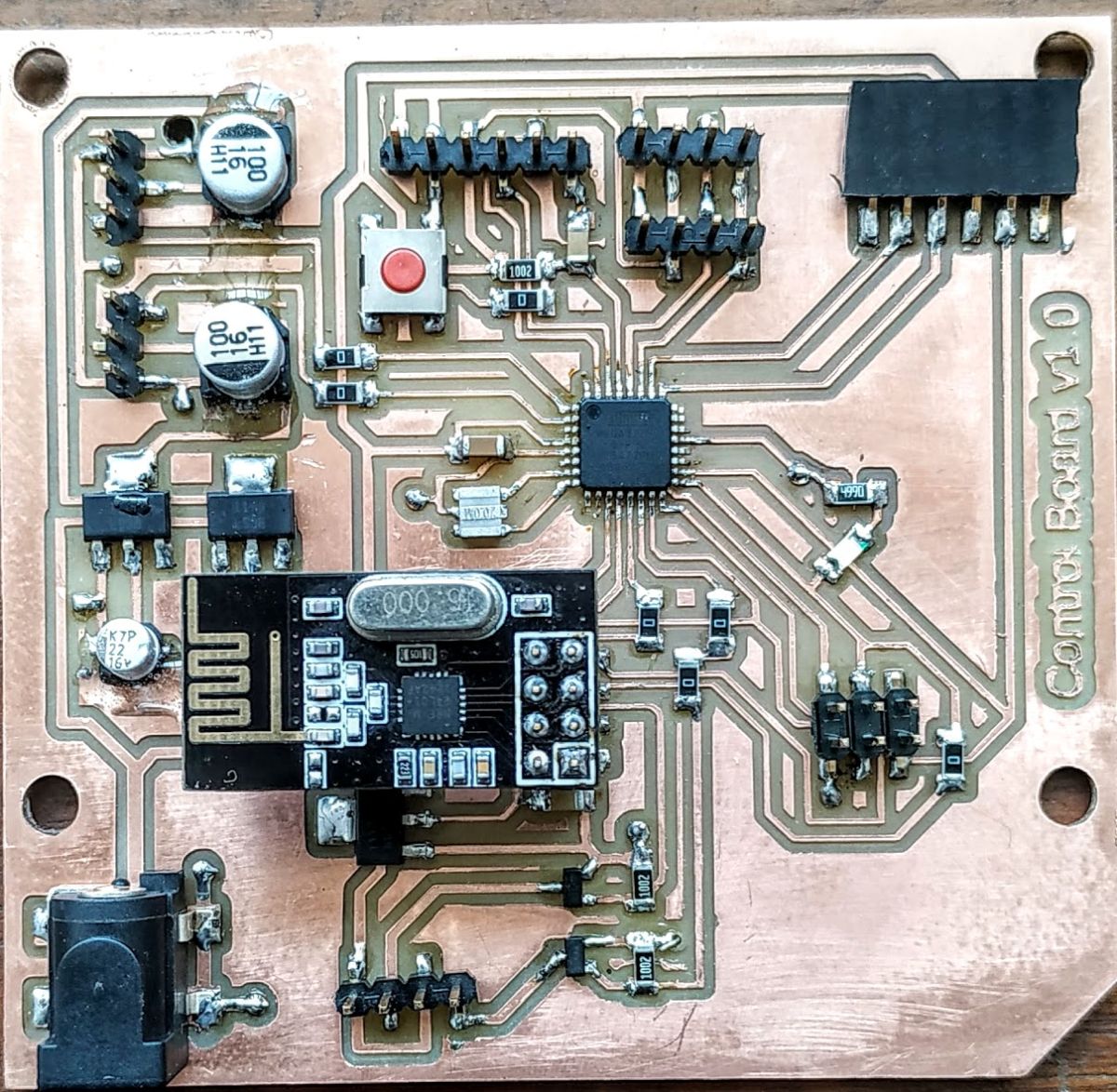
Features:
- Atmega328p 20MHz running on 5v
- Seperate 3.3v power for nRF24L01+
- Seperate power management for MG995 Servos using LM2940
- Control Circuit for 12v LED strips using N-Mosfets
- Onboard Devices: nRF24L01+, connecting port for HC-05
- Hardware i2c and Serial pinouts
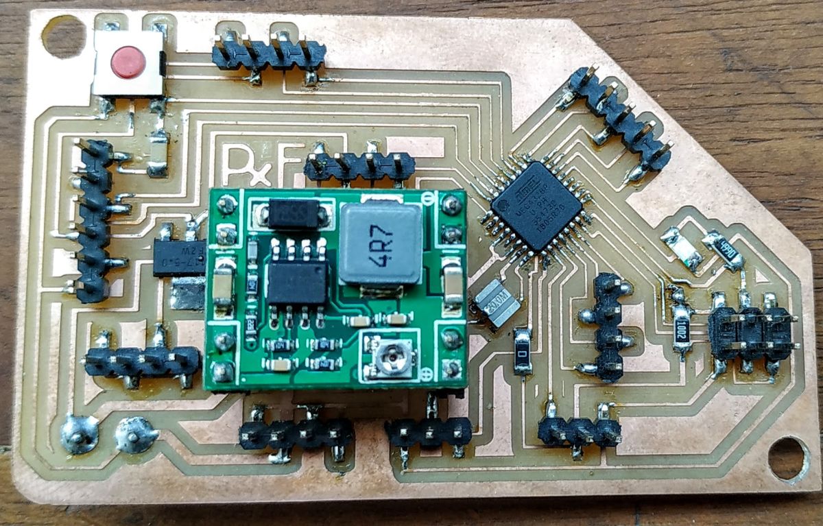
Features:
- Atmega328p 20MHz running on 5v
- Seperate High Current Power management for Addressable LED strips
- Hardware i2c and Serial pinouts
- Pinouts for ESC to drive a BLDC motor
- Pinouts for Optical Encoders on Interrupt pins
Board 1: Passing accelerometer data through nRF24L01+
Target Board
I designed the board around the ADXL345 and the nRF24L01+. As they required 3.3v power and we dont have logic level shifters at the lab, I used an atmega328p with an 8MHz resonator to run at 3.3v. I kept a seperate AMS1117 to power the nRF24L01+ module as I read that they get a bit fussy if proper power is not supplied.
I used Sparkfun’s ADXL345 breakout board as a reference for interfacing the ADXL345 chip. I tied pin 7 with VCC which enabled i2c mode and added noise filtering capacitors of 0.1uF and 10uF near the chip.
The board can be run on battery power as the voltage level needs to be just above 3.3 to work.
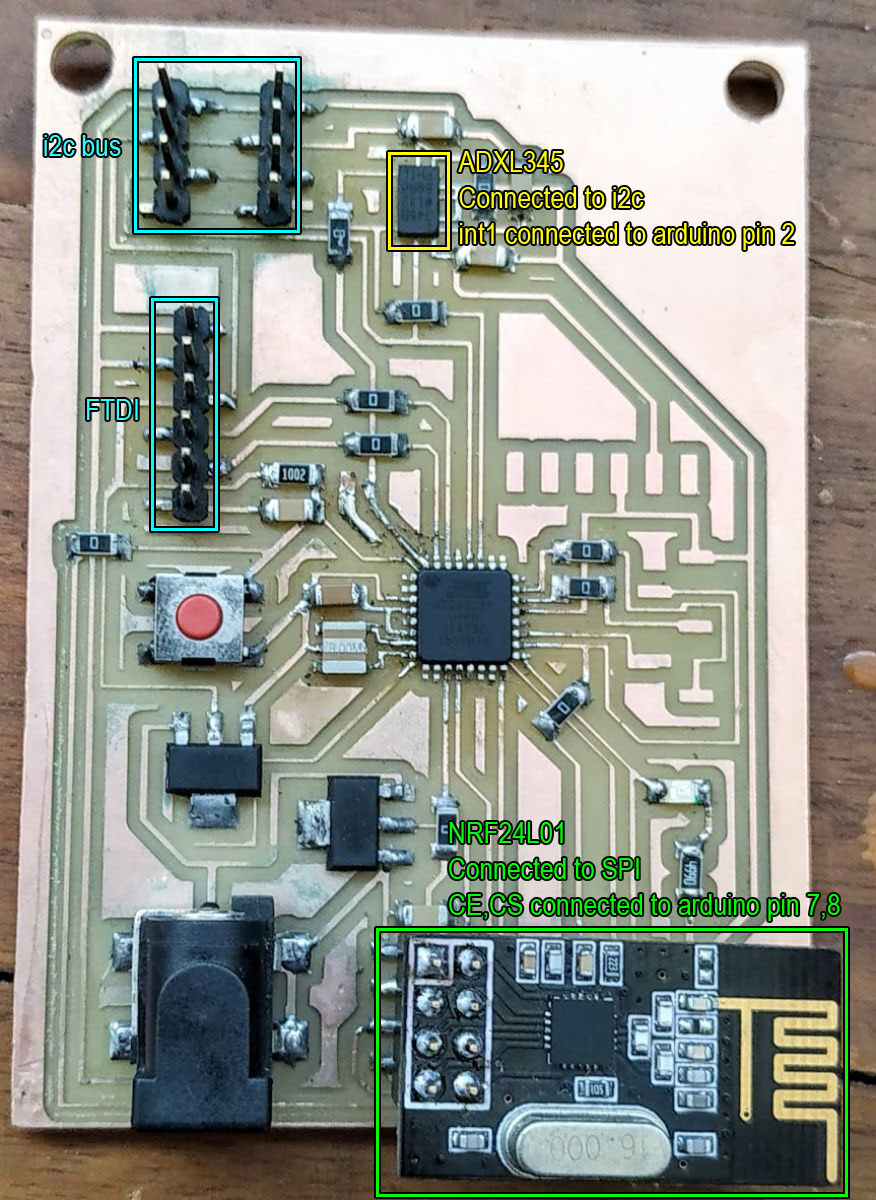
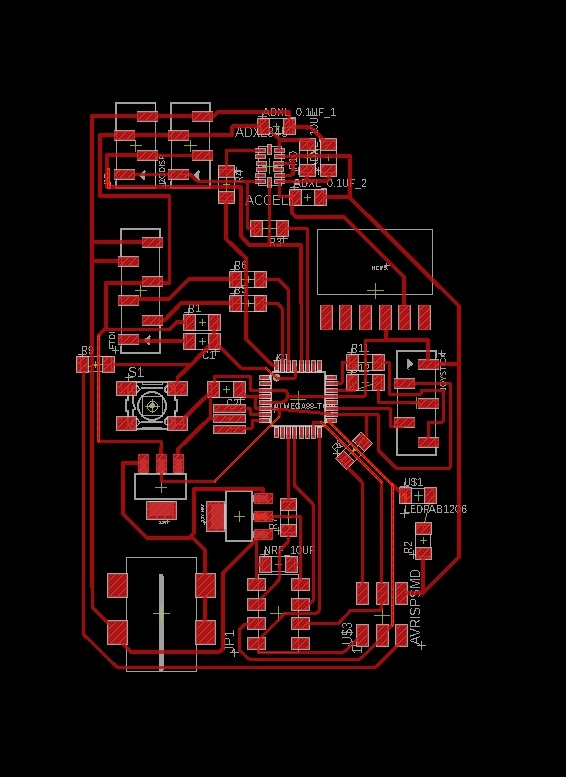
ADXL345 interfacing
->Checking if Accelerometer is Detected:
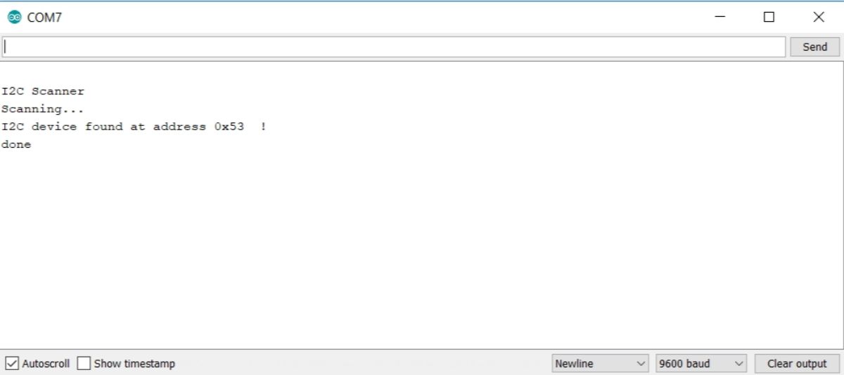
Since this was the first time I soldered a component without any legs, I wanted to check if my accelerometer was being detected as an i2c device, so I used the i2c Scanner code from Arduino Playground and it seemed to be getting detected at addres 0x53.
Reading Accelerometer Data:
To read the accelerometer data, I used the Sparkfun ADXL345 Library. It had many smart features like tap, double tap, activity, inactivity and freefall detection. But for now, I’ll just be using the following methods to get the x,y,z data.
Important LibraryFunctions Used
- ADXL345 adxl = ADXL345(); [Used to initiate communication in i2c mode]
- adxl.powerOn();
- adxl.setRangeSetting(2);[set’s the reading range. Lower range gives finer resolution, higher range measures larger accelerations; options are 2,4,8,16]
- adxl.readAccel(&int1 , &int2, & int3); [Reads and stores accelerometer data into three integers]
Download simpleXYZread_adxl345.ino
nRF24L01+ Interfacing
Transmitting an array of 3 integers Using the RF24 Library
For the nRF24L01+ modules, I used the RF24 library. I followed this youtube video to use the ‘getting started’ example to write my own code to transmit an integer array of size 3.
The code has two parts, the transmit part and the recieve part. This board will be using the transmit part.
Download nrf_simpleTransmit.ino
Important LibraryFunctions Used
-
RF24 radio(7,8); [Used to initate the nRF module, CE/CS pins)
-
byte addresses[][6] = {“1Node”,“2Node”}; [Assigning the addresses on the radios used]
-
radio.begin();
radio.setPALevel(RF24_PA_MAX); [Use RF24_PA_MIN if you don’t have power regulation for the nRF module]
radio.setDataRate(RF24_2MBPS); [define data rate]
radio.setChannel(124); [set the channel to transmit the data to] -
radio.openWritingPipe(addresses[1]);
radio.openReadingPipe(1, addresses[0]); [Open the writing and reading pipes, a bit like tx and rx in serial. Use alternating addresses in the recieve part of the code.] -
radio.stopListening(); [Stop listening before sending data]
-
radio.write( &data , sizeof(int[3])) [Send ‘data’, an integer array of size 3 ]
Final Code for Board 1:
Transmitting ADXL345 data using nRF24L01+(merging both of the codes)
Board 2: Recieving the data and passing it through i2c
Target Board:
I designed this board for our upcoming machine design project.
It has an nRF24L01+ module connected on the SPI bus, header pins for the i2c bus, FTDI pinout and a connector for an HC-05 module which I will be using for this week’s group work.
It has power management circuitry to drive two high current MG995 servos using LM2940 regulators. It also has two NDS355AN N- mosfets to control two 12v LED strips.
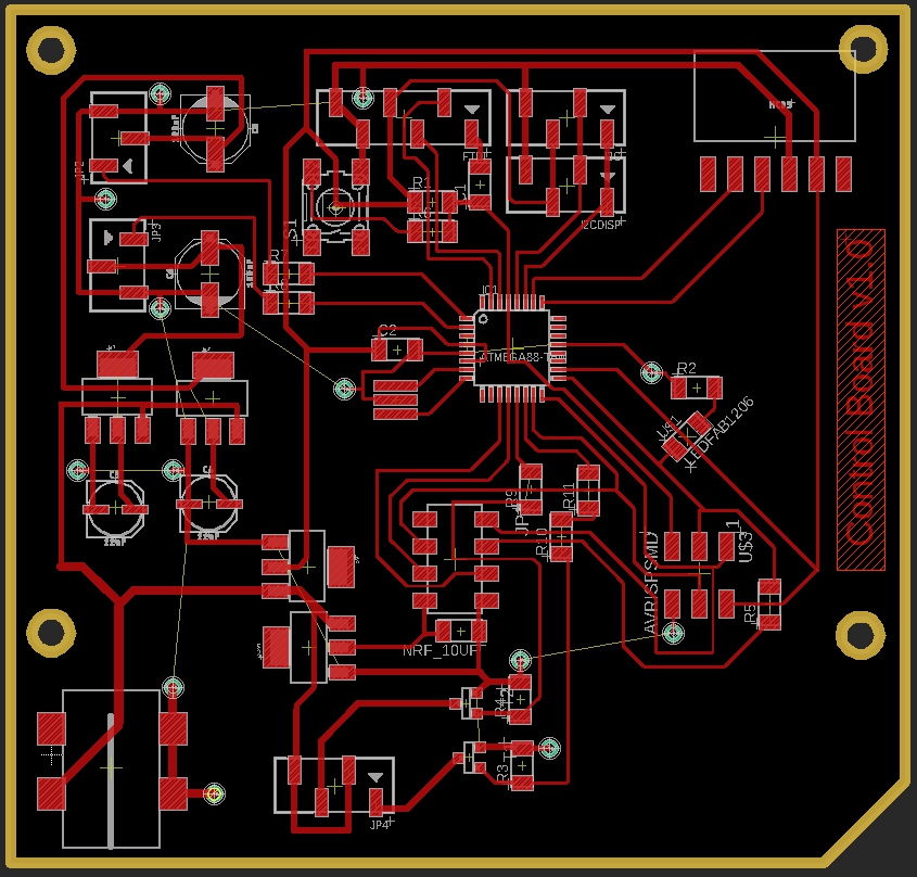
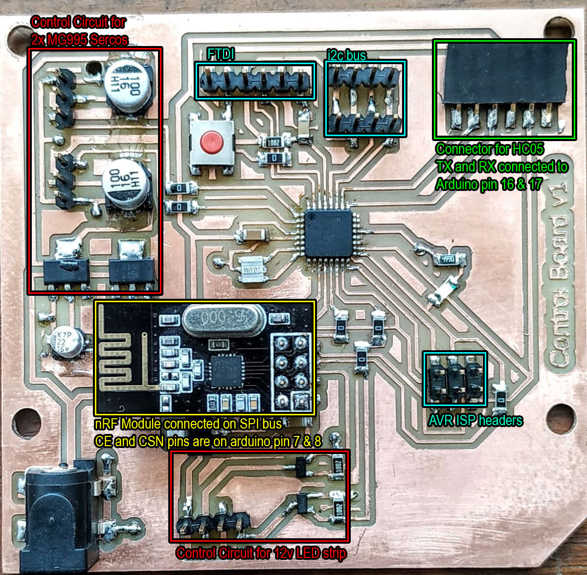
I used a double sided FR1 board to make this board and used the copper on the other side as a common ground plane. This helped me reduce the number of jumper resistors and also provided great thermals.
Recieving Accelerometer Data through nRF24L01+
Download nrf_simpleRecieve.ino
Important LibraryFunctions Used
-
RF24 radio(7,8); [Used to initate the nRF module, CE/CS pins)
-
byte addresses[][6] = {“1Node”,“2Node”}; [Assigning the addresses on the radios used]
-
radio.begin();
radio.setPALevel(RF24_PA_MAX); [Use RF24_PA_MIN if you don’t have power regulation for the nRF module]
radio.setDataRate(RF24_2MBPS); [define data rate]
radio.setChannel(124); [set the channel to transmit the data to] -
radio.openWritingPipe(addresses[0]);
radio.openReadingPipe(1, addresses[1]); [Using alternating addresses in this part of the code.] -
radio.startListening(); [start listening for data]
-
radio.read( &data , sizeof(int[3])) [Read the received ‘data’, an integer array of size 3 ]
Sending an integer array through i2c (Master side)
Download simple_i2c_master_array.ino
Final Code for Board 2
Board 3: Recieving i2c data and Writing it on Serial Monitor
Target Board:
I’ll just be using this board I made during the output week to read the data over i2c and print it on my Serial monitor. All details about this board can be found here.
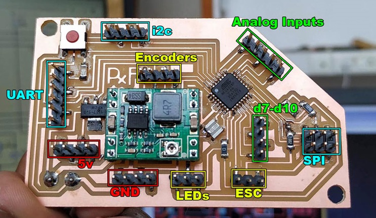
Recieving data from i2c bus: (slave side) and printing it on serial
Download simple_i2c_slave_array.ino
Hero Shots
Downloads
Datasheets:
Eagle Project Folders:
Code:
- Download i2c Scanner.ino
- Download simpleXYZread_adxl345.ino
- Download nrf_simpleTransmit.ino
- Download nrf_simpleRecieve.ino
- Download simple_i2c_master_array.ino
- Download simple_i2c_slave_array.ino
Learning Outcomes
- I learnt how to use the nRF24L01+ modules.
- I learnt power management for 3.3v components on a 5v board.
- I learnt how to use the widely used RF24 library
- I learnt how to network between multiple protocols like i2c, serial and rf using RF24.